
Related Manuals for DigiTech XC0450


Summary of Contents for DigiTech XC0450
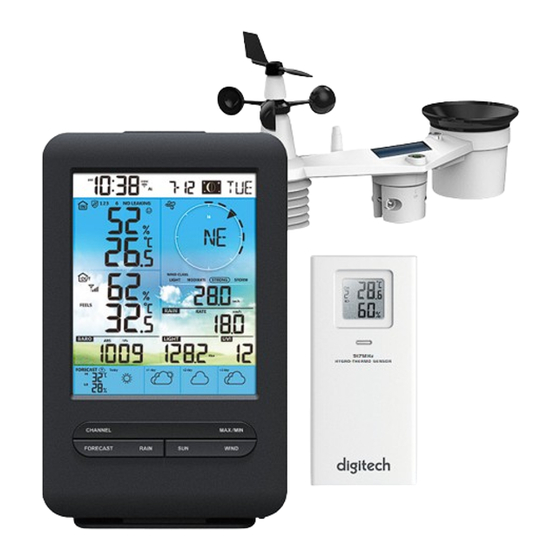
- Page 1 WiFi Digital Weather Station with 4 Day Forecasting 9 17 MHz H Y GRO -T H ERM O SEN SOR Model: XC0450 User Manual...
-
Page 2: Table Of Contents
TABLE OF CONTENTS 1. INTRODUCTION ..............4 1.1 QUICK START GUIDE . - Page 3 7. PROWEATHERLIVE (PWL) LIVE DATA & OPERATION ........28 7.1 VIEW LIVE DATA .
-
Page 4: Introduction
- The AC/DC adaptor of apparatus should not be obstructed OR should be easily accessed during intended used. - To be completely disconnect the power input, the AC/DC adaptor of apparatus shall be disconnected from the mains. CAUTION - Danger of explosion if battery is incorrectly replaced. Replace only with the same or equivalent type. - Battery cannot be subjected to high or low extreme temperatures, low air pressure at high altitude during use, storage or transportation. -
Page 5: Quick Start Guide
QUICK START GUIDE station, and upload to the Internet, along with references to the pertinent sections. Step Description Section Power up the 7-in-1 sensor array 3.1.3 Power up the display console and pair with sensor array Manually set date and time (This part is unnecessary if the weather 4.4.1 station is connected to PWL later) Reset the rain to zero... -
Page 6: Getting Started
GETTING STARTED WIRELESS 7-IN-1 SENSOR 1. Rain collector 11. [ RESET ] key 6. Wind cups 2. Balance indicator 7. Antenna 12. Battery door 3. Solar panel 8. Mounting clamp 13. Drain holes 4. UVI / light sensor 9. Radiation shield and 14. -
Page 7: Install Rain Gauge Funnel
3.1.2 INSTALL RAIN GAUGE FUNNEL Install the rain gauge funnel and rotate clockwise to lock the funnel to the sensor array Step 2 Lock Step 1 3.1.3 INSTALL BATTERIES Unscrew the battery door at bottom of unit. Insert the 3 AA batteries (non-rechargeable) according to the +/- polarity indicated. -
Page 8: Direction Alignment
NOTE: - Any metal object can attract lightning strikes, including your sensor-array mounting pole. Never install sensor-array in stormy days. - If you want to install a sensor-array on a house or building, consult a licensed electrical engineer to ensure proper grounding. -
Page 9: Recommendation For Best Wireless Communication
Model No of channel Description Image C3130A Thermo-Hygrometer sensor 868MHz HYGR O- THERMO SENSO C3133A High Precision Thermo-Hygrometer sensor 868MHz HYGR O- THERMO SENSO HIGH PRECISION Up to 7 sensors 868MHz SOIL SENSOR C3127A Soil Moisture and Temperature Sensor C3107B Pool Sensor Up to 7 868MHz... -
Page 10: Setup The Console
4. Barriers. Radio signal are blocked by metal barriers such as aluminum cladding. Please align the sensor array and display console to get them in clear line of sight through window if you through these building materials Materials Signal strength reduction Glass (untreated) Wood Plasterboard / drywall... -
Page 11: Setup Display Console
3.4.2 SETUP DISPLAY CONSOLE 1. Once the console power up, all the segments of the LCD will be shown. 2. The console will automatically start AP mode and show the "AP" icon on the screen, you can follow the section 6 to setup the WI-FI connection. Start up screen (with 7-in-1 sensor connected) NOTE: If no display appears when power up the console, you can press [ RESET ]... -
Page 12: Display Console Functions And Operation
DISPLAY CONSOLE FUNCTIONS AND OPERATION SCREEN DISPLAY 1. Time & Data, moon phase 6. Wind speed 2. Indoor / CH temperature & humidity 7. Rainfall & Rain rate 3. Outdoor temperature & humidity 8. Light intensity 4. Barometer 9. UV index 5. -
Page 13: Console Features
CHANNEL Press this button to switch between indoor and channels readings FORECAST RAIN Press to switch between Rain Rate, rainfall MAX / MIN Since last reset Beaufort Scale WIND Press and hold 2 seconds to switch wind direction between language and 360 bearing Press to switch between Solar Light Intensity and Sunburn time Table stand... -
Page 14: High / Low Temperature Forecast For Today & Next 3 Days
setup), the console indicates the weather forecasts of today and next 3 days. Multi day weather forecast section Weather forecast with High (HI) and Low (LO) temperatures is default mode in this section, if update is normal, the 4.3.2 HIGH / LOW TEMPERATURE FORECAST FOR TODAY & NEXT 3 DAYS the HI and LO temperatures from today to the next 3 days, simply press the [ FORECAST ] key as shown below. -
Page 15: Outdoor Temperature, Humidity & Temperature Index
NOTE: refer to section 5 and 6 for the WI-FI and PWL setup. icon will disappear. 4.3.4 OUTDOOR TEMPERATURE, HUMIDITY & TEMPERATURE INDEX 1. Outdoor sensor signal indicator to show the signal 2. Outdoor sensor low battery indicator 3. Temperature index mode indicator 4. -
Page 16: Indoor / Channels Temperature & Humidity
4.3.4.4 DEW POINT when it forms on a solid surface. - The dew point temperature is determined by the temperature & humidity data from wireless 7-IN-1 sensor. 4.3.5 INDOOR / CHANNELS TEMPERATURE & HUMIDITY This section can show reading and status of the indoor, optional hygro-thermo sensor(s) and water leak sensor(s). -
Page 17: Water Leak (Optional Leak Sensor)
4.3.7 WATER LEAK (OPTIONAL LEAK SENSOR) You can add up to 7 additional Water Leak sensors (optional, refer to section 3.2) The channel number(s) of the corresponding water leak sensor(s) added to the console will be shown with the NO LEAKING icon. When water leaking is detected, the channel number of the sensor NOTE: When low battery is detected, the channel number of the sensor detecting the low battery... - Page 18 User can change to wind direction shown in 360 degrees. Press and hold [ WIND ] / INDEX ] or [ / MODE ] key to select the display format between 16-point direction and 360 degrees. 4.3.8.4 BEAUFORT SCALE TABLE (Hurricane force).
-
Page 19: Barometric Pressure
Some twigs broken from trees. Gale seriously impeded Some branches break off trees, and some Strong gale Trees are broken off or uprooted, Storm structural damage likely. Violent storm damage likely. Hurricane force and structures. Debris and unsecured 4.3.9 BAROMETRIC PRESSURE The atmospheric pressure is the pressure at any location of and gradually decreases as altitude increases. -
Page 20: Light Intensity, Uv Index & Sunburn Time
NOTE: Erroneous readings may occur during the installation of the 7-in-1 sensor array. Once the afresh. 4.3.11 LIGHT INTENSITY, UV INDEX & SUNBURN TIME This section of display show the sunlight intensity, UV index and sunburn time. 4.3.11.1 LIGHT INTENSITY & SUNBURN TIME MODE: During light intensity mode, press [ SUN ] key to switch between sunlight intensity and sunburn time... -
Page 21: Moon Phase
4.3.13 MOON PHASE The moon phase is determined by time Northern Southern Moon Phase and date of the console. The following Hemisphere Hemisphere table explains the moon phase icons of New Moon the Northern and Southern Hemispheres. Please refer to section 6.3 web interface Waxing Crescent about how to setup for the Southern Hemisphere. -
Page 22: Other Setting
OTHER SETTING 4.4.1 TIME, DATE AND GENERAL SETTING Press and hold the [ SET ] button for 2 seconds to enter the setting mode. Press [ / INDEX ] or / MODE ] [ SET ] to proceed with next step of the setting. Please refer to following setting procedures. -
Page 23: Unit Setting
- By pressing and hold [ALARM / SNOOZE] the next day - By pressing [ ALARM ] NOTE: - The snooze could be used continuously in 24 hours. - During the snooze, the alarm icon “ 4.4.3 UNIT SETTING Use the [ UNIT ] key to change the unit of measure of the reading on the console display. Below is the operation step: - Press and hold [ UNIT ] key for 2 seconds to enter the unit setting mode. - Page 24 Edit Devices" in the pull down menu. Dashboard Account Edit Devices Unit & Display Alert Setting Weather Server Data Export Help Log Out +Add FINISH" to create the station tab. 4. Click the " Edit " on the top right corner of the station tab. NOTE: For example, 33.8682 South is “-33.8682”...
-
Page 25: Connect Console To Wi-Fi
6. In the "SETUP" page mentioned in section 6.3, enter the Station ID and key assigned by ProWeatherLive PWL2345678 Station ID: 112233 Station key: CONNECT CONSOLE TO WI-FI CONSOLE IN ACCESS POINT MODE and " " icon to signify that it has entered AP (Access Point) mode, and is ready for WI-FI settings. -
Page 26: Setup The Weather Server Connection
SETUP THE WEATHER SERVER CONNECTION Enter the information into the following web interface "SETUP" page. Ensure all information is entered prior to pressing Apply SETTINGS Press "ADVANCED" icon to SETUP ADVANCED Select setup UI display language Language: English WiFi Router setup Press to search router Select router (SSID) for connection Search... -
Page 27: Advance Setting In Web Interface
ADVANCE SETTING IN WEB INTERFACE Press "ADVANCED" SETTINGS Press "SETUP" icon to setup page SETUP ADVANCED Select setting unit Temperature Indoor Current offset: 0 Current offset: 0 Outdoor Current offset: 0 Current offset: 0 CH 1 Current offset: 0 Current offset: 0 temperature calibration CH 2 Current offset: 0... -
Page 28: Calibration
6.4.1 CALIBRATION 2. Once completed, press at the bottom of the SETUP page. Apply Apply icon in SETUP page. NOTE: PROWEATHERLIVE (PWL) LIVE DATA & OPERATION VIEW LIVE DATA page. NOTE: Please press "Help" in the UPLOAD TO OTHER WEATHER SERVERS more information about their setup (e.g. -
Page 29: Maintenance
MAINTENANCE FIRMWARE UPDATE Browse Upload to console Firmware update in ADVANCED page 8.1.1 FIRMWARE UPDATE STEP 2. Set the console into AP (access point) mode then connect the PC/Mac to the console (refer to section 6.1 and 6.2). Browse your PC/Mac. 5. -
Page 30: Re-Pairing The Sensor(S) Manually
8.2.1 RE-PAIRING THE SENSOR(S) MANUALLY sensors, re-synchronization must be done manually. 1. Change all the batteries to new ones in the low battery sensor(s). 2. Press [ SENSOR / WI-FI ] key on the console to enter sensor synchronization mode (as RESET AND FACTORY RESET To reset the console and start again, press the [ RESET ] key and then unplug the adapter. -
Page 31: Troubleshoot
TROUBLESHOOT Problems Solution 7-in-1 wireless sensor 1. Make sure the sensor is within the transmission range is intermittent or no 2. If it still does not work, reset the sensor and resynchronize with console connection Additional wireless 1. Make sure the sensor(s) is/are within the transmission range sensor(s) is/are 2. -
Page 32: Specifications
SPECIFICATIONS 10.1 CONSOLE 118 x 192.5 x 21mm (4.6 x 7.6 x 0.8 in) without attach table Dimensions (W x H x D) stand Weight 269g (with battery) Main power DC 5V, 1A adapter Backup battery CR2032 Operating temperature range -5˚C ~ 50˚C Standard 802.11 b/g/n... - Page 33 Memory modes Historical data of past 24 hours, daily Max / Min Indoor Temperature (Note: Data detected by console) Temperature unit °C and °F Accuracy Resolution °C / °F (1 decimal place) Indoor Humidity (Note: Data detected by console) Humidity unit Accuracy Resolution Memory modes...
-
Page 34: Wireless 7-In-1 Sensor
Resolution 1 decimal place LIGHT INTENSITY : Data detected by 7-in-1 sensor) (Note Light intensity unit Klux, Kfc and W/m² Display range 0 ~ 200Klux Resolution Klux, Kfc and W/m² (2 decimal place) 10.2 WIRELESS 7-IN-1 SENSOR Dimensions (W x H x D) 390 x 217 x 165 mm (15.3 x 8.5 x 6.5in) Weight 543g (with Batteries)
Need help?
Do you have a question about the XC0450 and is the answer not in the manual?
Questions and answers
Once WiFi connected, unable to connect to app