Table of Contents
Advertisement
Quick Links
Installation and Operation Instructions
Installation and Operation
Instructions for
Hydronic Boiler
Model BMT2H
Water Heater
Model BMT2V
Sizes 200, 300, 400
This product must be installed and serviced by a professional service technician,
FOR YOUR SAFETY:
qualified in hot water boiler installation and maintenance. Improper installation and/or operation could
create carbon monoxide gas in flue gases which could cause serious injury, property damage, or
death. Improper installation and/or operation will void the warranty. For indoor installations, as an
additional measure of safety, Bradford White strongly recommends installation of suitable Carbon
Monoxide detectors in the vicinity of this appliance and in any adjacent occupied spaces.
WARNING
If the information in this manual is not
followed exactly, a fire or explosion may
result causing property damage, personal
injury or loss of life.
Do not store or use gasoline or other
flammable vapors and liquids in the vicinity of
this or any other appliance.
WHAT TO DO IF YOU SMELL GAS
• Do not try to light any appliance.
• Do not touch any electrical switch; do not
use any phone in your building.
• Immediately call your gas supplier from
a nearby phone. Follow the gas supplier's
instructions.
• If you cannot reach your gas supplier, call
the fire department.
Installation and service must be performed
by a qualified installer, service agency, or gas
supplier.
AVERTISSEMENT
Assurez-vous de bien suivres les instructions
données dans cette notice pour réduire au
minimum le risque d'incendie ou d'explosion ou
pour éviter tout dommage matériel, toute blessure
ou la mort.
Ne pas entreposer ni utiliser d'essence ni d'autres
vapeurs ou liquides inflammables dans le voisinage
de cet appareil ou de tout autre appareil.
QUE FAIRE SI VOUS SENTEZ UNE ODEUR DE GAZ:
• Ne pas tenter d'allumer d'appareils.
• Ne touchez à aucun interrupteur. Ne pas vous
servir des téléphones dansle bâtiment où vous
trouvez.
• Appelez immédiatement votre fournisseur de
gaz depuis un voisin. Suivez les instructions
du fournisseur.
• Si vous ne pouvez rejoindre le fournisseur de
gaz, appelez le sservice des incendies.
L'installation et l'entretien doivent être assurés par
un installateur ou un service d'entretien qualifié ou
par le fournisseur de gaz.
Document 1244C
Advertisement
Table of Contents

Subscribe to Our Youtube Channel
Related Manuals for Bradford White Brute Deluxe BMT2H0200


Summary of Contents for Bradford White Brute Deluxe BMT2H0200
- Page 1 Improper installation and/or operation will void the warranty. For indoor installations, as an additional measure of safety, Bradford White strongly recommends installation of suitable Carbon Monoxide detectors in the vicinity of this appliance and in any adjacent occupied spaces.
-
Page 2: Table Of Contents
Page 2 Bradford White Corp TABLE OF CONTENTS SECTION 5 Electrical Connections ..24 SECTION 1 General Information ....3 Main Power ..........24 Introduction ..........3 Field Wiring ..........24 Model Identification ........4 Low Water Cut-Off ........24 Warranty ............ 4 Logic Diagrams ........ -
Page 3: Section 1 General Information
Where differences exist between the detailed in this manual, or the Bradford White application of the appliances and their operation, warranty may be voided. The installation the sections pertinent to only one appliance or the must conform to the requirements of the local other will be so identified. -
Page 4: B Model Identification
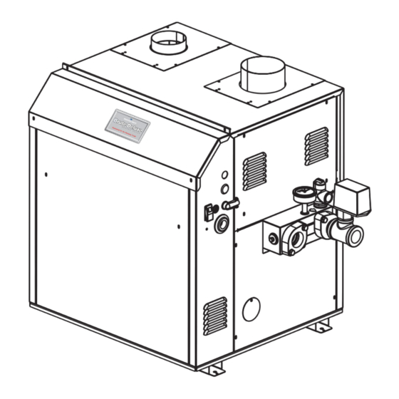
Claims must include the serial number 1-4 Model Series Designation and model (this information can be found on the rating B M T 2 = Bradford White, Brute Deluxe plate), installation date, and name of the installer. Usage... - Page 5 Page 5 Brute Deluxe 200, 300, 400), Install & Operating Dimensions shown in inches, cm. Combustion Air Horizontal Vent Connection Model Connection (Cat III) Vent Pipe Size 20.5 26.5 33.6 *Air and vent connections may be on top or back of the Brute Deluxe, and are field convertible. Figure 1.
- Page 6 Page 6 Bradford White Corp Dimensions shown in inches, cm. Combustion Air Horizontal Vent Connection Model Connection (Cat III) Vent Pipe Size 20.5 26.5 33.6 *Air and vent connections may be on top or back of the Brute Deluxe, and are field convertible.
-
Page 7: F Locating Pump-Mounted Water Heater With Respect To Storage Tank(S)
Page 7 Brute Deluxe 200, 300, 400), Install & Operating Intake Side Wall Heater Vent Collar Horizontal Air Collar Max. Pipe Max. No. Side Vent Combustion Size Size Vent Pipe & Pipe Length of Elbows Terminal Air Terminal Diameter Diameter Part Number Part Number CA003101... -
Page 8: Section 2 Venting And Combustion Air
Page 8 Bradford White Corp SECTION 2 Venting and Method 2: One permanent opening, commencing Combustion Air within 12 inches (30 cm) of the top of the enclosure, shall be permitted. The opening shall directly WARNING communicate with the outdoors or shall communicate... -
Page 9: Intake Combustion Air
If the Brute Deluxe’s it must be taken from out-of-doors by means of the vertical vent system does not satisfy the criteria for Bradford White horizontal wall terminal (see Table Category I venting, it must be vented as a Category III When taken from the roof, a field-supplied rain cap or system. -
Page 10: Category Iii Vent
CSA B149.1 how a blocked vent safety system should be connected and local applicable codes. Consider the following to a Bradford White product, please call Applications when installing the terminal: Engineering at the Rochester phone number on the... - Page 11 Page 11 Brute Deluxe 200, 300, 400), Install & Operating U.S. Installations (see note 1) Canadian Installations (see note 2) A= Clearance above grade, veranda, porch, 12 inches (30 cm) 12 inches (30 cm) deck, or balcony B= Clearance to window or door that may Direct Vent Only: 12 inches (30 cm) be opened Other Than Direct Vent: 4 feet (1.2 m) below or...
- Page 12 Page 12 Bradford White Corp 6. If the boiler or water heater uses ducted detector with alarm and battery back-up may be combustion air from an intake terminal located on installed on the next adjacent floor level. the same wall, locate the vent terminal at least 3 b.
-
Page 13: Side Wall Combustion Air Terminal
2.C.2 Side Wall system. Combustion Air Terminal Visually inspect the venting system for proper The Bradford White side wall combustion air terminal size and horizontal pitch and determine there is (listed in Table 1) must be used when the unit... -
Page 14: E Vent Terminals For Outdoor Units
Sceller toutes les ouvertures non utilisées du vent opening. système d'évacuation. If local codes allow, Bradford White kits are Inspecter de façon visuelle le système not required for outdoor units. The installer may use d'évacuation pour déterminer la grosseur et 12"... -
Page 15: Section 3 Gas Supply And Piping
Page 15 Brute Deluxe 200, 300, 400), Install & Operating SECTION 3 Gas Supply and Piping 3.A Gas Supply and Piping pressures in excess of 0.5 psig (3.45 kpa). Gas piping should be supported by suitable The unit must be isolated from the gas supply hangers or floor stands, not by the appliance. -
Page 16: Section 4 Water Connections
Page 16 Bradford White Corp SECTION 4 Water Connections — 4.A Brute Deluxe Boiler 4.A.3 Water Flow Requirements — Boiler 4.A.1 Heating System Piping: A hydronic heating (closed loop) application Hot Supply Connections — Boiler recirculates the same fluid in the piping system. As a... -
Page 17: B Water Connections - Brute Deluxe Water Heater
Page 17 Brute Deluxe 200, 300, 400), Install & Operating 4.B Water Connections — Model 20°F 25°F 30°F 35°F (Size) Brute Deluxe Water Heater flow flow flow flow feet feet feet feet 4.B.1 Water System Piping — Water Heater Hot water piping should be supported by suitable hangers or floor stands. - Page 18 Page 18 Bradford White Corp Figure 6. Hydronic Piping — Multiple Boilers, Low Temperature System. Figure 7. Hydronic Piping — One Boiler, Multi-Temperature System.
- Page 19 Page 19 Brute Deluxe 200, 300, 400), Install & Operating Figure 8. Hydronic Piping — Primary-Secondary, Reverse-Return. Figure 9. Hydronic Piping — Primary-Secondary, Reverse-Return, Low Temperature.
-
Page 20: Hot Water Supply Piping -Water Heater
Bradford White for additional information. enough to prevent tube erosion. For extremely soft or hard water, cupro-nickel tubes are available. Contact a Bradford White representative if you have questions or concerns about water quality. Pump-mounted water heaters can be ordered with standard pumps for soft or normal water. - Page 21 Page 21 Brute Deluxe 200, 300, 400), Install & Operating Model Temp Rise °F Temp. Rise °C (Size) Notes: 1. S = soft water (1 to 7.5 grains hardness) 2. N = normal water (7.6 to 17 grains hardness) 3. H = hard water (more than 17 grains hardness) 4.
- Page 22 Page 22 Bradford White Corp KEY: WATER CATEGORY GRAIN HARDNESS PER GALLON S = SOFT 1 THROUGH 7.5 N = NORMAL 7.6 THROUGH 17 H = HARD OVER 17 PPM / 17.1 = Grains Per Gallon CAUTION: THIS DRAWING SHOWS SUGGESTED...
- Page 23 Page 23 Brute Deluxe 200, 300, 400), Install & Operating CAUTION: THIS DRAWING SHOWS SUGGESTED KEY: PIPING CONFIGURATION AND VALVING, CHECK WATER CATEGORY WITH LOCAL CODES AND ORDINANCES FOR GRAIN HARDNESS PER GALLON ADDITIONAL REQUIREMENTS. S = SOFT 1 THROUGH 7.5 N = NORMAL 7.6 THROUGH 17 H = HARD...
-
Page 24: Section 5 Electrical Connections
Page 24 Bradford White Corp SECTION 5 Electrical Connections WARNING The appliance must be electrically grounded in Single pole switches, including those of safety accordance with the requirements of the authority controls and protective devices must not be wired in a having jurisdiction or, in the absence of such grounded line. -
Page 25: Logic Diagrams
Page 25 Brute Deluxe 200, 300, 400), Install & Operating Logic Diagrams. 120 VAC MAIN PWR SW HSI IGNITOR 120 VAC 120 VAC IGN CTL IGN CTL IGN CTL IGN CTL POWER MAIN PWR SW HSI IGNITOR IGN/120 IGN/FS 120 VAC IGN CTL IGN CTL IGN CTL... -
Page 26: Wiring Diagrams
Page 26 Bradford White Corp Wiring Diagrams. Figure 16. Wiring Diagram, Boiler. - Page 27 Page 27 Brute Deluxe 200, 300, 400), Install & Operating Figure 17. Wiring Diagram, Volume Water Heater.
-
Page 28: Section 6 Operating Instructions
Page 28 Bradford White Corp SECTION 6 Operating Instructions attempt to light two more times, and then will go into lockout mode. Second, turn the power off and then on again, open the manual gas valve 6.A Filling the Boiler System and allow the unit to light. -
Page 29: Temp Control On Boilers
Page 29 Brute Deluxe 200, 300, 400), Install & Operating LEDs State Description 1. Power Auto Boiler Target Setpoint: Space Heating: 2. Heat – On = call for heat; Flashes for Boiler The boiler target temperature is automatically sensor error 3. -
Page 30: Temp Control On Water Heaters
Page 30 Bradford White Corp Boiler Minimum target is set to Boiler Minimum + 1. Connect the system sensor on the SYS and COM differential/2. terminals. 2. Target Max - The boiler target maximum is 2. Install the sensor into a well in the location used to the point at which the stages will start to turn off to control water temperature. -
Page 31: D Sequence Of Operation
Page 31 Brute Deluxe 200, 300, 400), Install & Operating detected, the gas valve will close and the ignition module will attempt ignition again (up to two more times, for a total of three attempts.) If all three attempts fail, the ignition control will lock out. If flame is sensed, the burner will continue to fire as long as there is a call for heat, and none of the safety circuit is interrupted. -
Page 32: High Altitude Adjustment And Set-Up
Page 32 Bradford White Corp with water and all air has been bled from both. and header gaskets for watertight integrity 24 Open all valves. hours after commissioning. If there are any signs 3. Observe all warnings on the Operating Instructions... -
Page 33: G Shutting Down The Brute Deluxe
7.B Appliance Maintenance and Component Description Only genuine Bradford White replacement parts should be used. Caution Label all wires prior to disconnection when servicing controls. Wiring errors can cause improper and dangerous operation. -
Page 34: Burners
Page 34 Bradford White Corp joints should be coated with piping compound resistant The gas and electric controls on the appliance to action of liquefied petroleum gas), and reinstall in are engineered for long life and dependable operation, reverse order. Turn on manual gas shutoff valve and... -
Page 35: Transformer
Page 35 Brute Deluxe 200, 300, 400), Install & Operating 7.B.7 Transformer screws that attach the top to the side panels. Remove the side panels. The Brute Deluxe’s transformer is not capable of supplying control voltage for external devices such Remove the heat exchanger from the unit. -
Page 36: Section 8 Trouble Shooting
15-second fan pre-purge, the ignitor will heat necessary to install a buffer tank in the system. Contact up for 40 seconds, and then the unit will light. your Bradford White representative to discuss possible If it does not, check the gas supply pressure to remedies. -
Page 37: Section 9 Replacement Parts
Only genuine Bradford White replacement parts should be used. 9.A General Information To order or purchase parts for the Bradford White Brute Deluxe, contact your nearest Bradford White dealer or distributor. If they cannot supply you with what you need, contact Customer Service (see back cover for address, telephone and fax numbers). - Page 38 Page 38 Bradford White Corp Item Description Model 200 Model 300 Model 400 JACKET COMPONENTS See Figure 20 Panel, Front, Jacket R2C3320 R3C3320 R4C3320 Panel, Rear, Jacket 2C3220 3C3220 4C3220 Panel, Top, Jacket 2C3021 3C3021 4C3021 Panel, Jacket, Control Access 2F3019 3F3019...
- Page 39 Page 39 Brute Deluxe 200, 300, 400), Install & Operating Item Description Model 200 Model 300 Model 400 GAS TRAIN COMPONENTS See Figure 22 Weldment, Gas Manifold, Main L0063702 L0063703 L0063704 Manifold, Gas, On/Off L0063414 L0063416 L0063418 Manifold, Gas, 2 Stage Left Bank L0063404 L0063413 L0063414...
- Page 40 Page 40 Bradford White Corp Figure 19. Combustion Chamber Components.
- Page 41 Page 41 Brute Deluxe 200, 300, 400), Install & Operating Figure 20. Jacket Components.
- Page 42 Page 42 Bradford White Corp Boiler Emersion Well This Side Volume Water Heater Emersion Well This Side Figure 21. Heat Exchanger Components.
- Page 43 Page 43 Brute Deluxe 200, 300, 400), Install & Operating ON/OFF 2 STAGE Figure 22. Gas Train Components.
- Page 44 Figure 23. Control Panel Components. Dimensions and specifications subject to change without notice in accordance with our policy of continuous product improvement. 200 Lafayette St. www.BradfordWhite.com Middleville, MI 49333 Warranty: (800) 531-2111 Litho in U.S.A. © Bradford White 1805 Document 1244C-BW...
Need help?
Do you have a question about the Brute Deluxe BMT2H0200 and is the answer not in the manual?
Questions and answers