Table of Contents
Advertisement
Quick Links
November, 2019
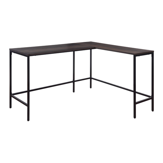
CNT41
CONTEMPO L DESK
Assembly Instructions - Important:
Carefully unpack and identify each component before attempting to assemble. Refer to parts list. Please take care when
assembling the unit and always set the parts on a clean, soft surface. If you require any assistance with assembly, parts or
information on other products, please visit our website: www.officestar.net or call or write us.
Advertisement
Table of Contents

Related Manuals for OSP Home Furnishings CONTEMPO CNT41


Summary of Contents for OSP Home Furnishings CONTEMPO CNT41
- Page 1 November, 2019 CNT41 CONTEMPO L DESK Assembly Instructions - Important: Carefully unpack and identify each component before attempting to assemble. Refer to parts list. Please take care when assembling the unit and always set the parts on a clean, soft surface. If you require any assistance with assembly, parts or information on other products, please visit our website: www.officestar.net or call or write us.
- Page 2 LIMITED WARRANTY OSP Home Furnishings™ warrants to the original purchaser that this product will be free from defects in material and workmanship as described below. OSP Home Furnishings™ will repair or replace, at its option, without charge to the original purchaser only, defective products or parts for one (1) year from the date of purchase.
- Page 3 3. Rename all English discriptions to French discriptions. PARTS (A) Top (1 PC) (B) Top (1 PC) (C) Left Leg Frame (1 PC) (D) Right Leg Frame (1 PC) (E) Middle Leg Frame (1 PC) (F) Left Front Upper Support (1 PC) (G) Left Back Upper Support (1 PC) (H) Left Lower Support (1 PC) (I) Right Front Upper Support (1 PC)
- Page 4 3. Rename all English discriptions to French discriptions. PARTS (K) Right Lower Support (1 PC) HARDWARE LIST DRAWING DESCRIPTION SIZE QUANTITY Bolt Ø1/4” x 1/2” 24 PCS + 2 EXTRA Bolt Ø1/4” x 1-3/16” 15 PCS + 2 EXTRA Cam Screw 4 PCS Cam Nut 2 PCS...
- Page 5 CAM LOCK INSTRUCTIONS...
- Page 6 STEP 1 DO NOT FULLY TIGHTEN BOLTS. STEP 2 DO NOT FULLY TIGHTEN BOLTS.
- Page 7 STEP 3 FULLY TIGHTEN CAM NUTS (4) USING PHILLIPS SCREWDRIVER (NOT PROVIDED). STEP 4 FULLY TIGHTEN ALL BOLTS.
- Page 8 STEP 5 IF NEEDED, ADJUST LEVELERS TO LEVEL.
Need help?
Do you have a question about the CONTEMPO CNT41 and is the answer not in the manual?
Questions and answers