Table of Contents
Advertisement
Quick Links
Thank you very much for purchasing this Panasonic product.
Please read these operating instructions carefully before operation and maintenance.
Also, be sure to read the "SAFETY PRECAUTIONS" section (P.2 ~ 5) before use.
Failure to comply with instructions could result in injury or property damage.
Please retain this booklet for future reference.
OPERATING INSTRUCTIONS
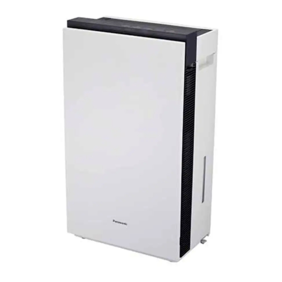
ziaino
Air Treatment Unit
®
Model No.
This product is for indoor use only
CONTENTS
.........................................................
●
................................................
●
●
...............................................................
●
F-JPW50H
.................................
.................................
...........................
.....................
.................................... 12
..........................................
........................... 26
.................................
...........................
.....................
..............................
.................................
.................................31 ~ 32
.............................................
2 ~ 5
6
6
7 ~ 10
11 ~ 12
13 ~ 15
16 ~ 18
......
19 ~ 26
............ 25
26
27
27
28
29
29 ~ 32
32
Advertisement
Table of Contents

Related Manuals for Panasonic ziaino F-JPW50H


Summary of Contents for Panasonic ziaino F-JPW50H
-
Page 1: Table Of Contents
● SPECIFICATIONS ……………………………………… Thank you very much for purchasing this Panasonic product. Please read these operating instructions carefully before operation and maintenance. Also, be sure to read the “SAFETY PRECAUTIONS” section (P.2 ~ 5) before use. Failure to comply with instructions could result in injury or property damage. -
Page 2: Safety Precautions
SAFETY PRECAUTIONS Please strictly follow Disconnect power supply before maintenance and filling water and water drainage. ■ For cleaning and descaling see "maintenance“ and regarding filling (water supply) see ■ “WATER SUPPLY/DRAINAGE METHOD”. If the supply cord is damaged, it must be replaced by the manufacturer, its service agent or ■... - Page 3 SAFETY PRECAUTIONS Please strictly follow WARNING For hospitals, rehabilitation ■ Make sure to disconnect the ■ centers or the like, please pay power plug before cleaning attention to the operating the product. places of this product. Make (Otherwise, the product might sure that customers with operate with the possibility of implanted medical...
- Page 4 SAFETY PRECAUTIONS Please strictly follow CAUTION Do not place the product in Do not push over or overturn ■ ■ the product. the incline and unstable place or at heights. (Otherwise, the water may spill out and fire, electric shock may occur or (Otherwise, the product wet furniture, etc.) may fall over and injury...
- Page 5 SAFETY PRECAUTIONS Please strictly follow CAUTION When draining the water, Do not add chemicals, air ■ ■ turn on the tap to flush the fresheners, essential oils, etc. sink clean. into the tank or tray. (Otherwise, toxic gas may be (Otherwise, the sink and water pipe produced, which is harmful to your may oxidize to form rust.)
-
Page 6: Setting Requirements
SETTING REQUIREMENTS When used beside a wall, etc. Do not set the product in the following places. ■ ■ Keep a safe distance during use as Where the product will be exposed directly to instructed below. sunlight, outlet of air conditioner or heat, etc. (Poor ventilation may cause the internal (Otherwise, deformation, deterioration, temperature of the main unit to rise, thus... -
Page 7: Each Parts Identification
EACH PARTS IDENTIFICATION Main unit Control panel Odor sensor Status indicator Humidity sensor Front panel Handle (left and right) Before the first use, please remove the cardboard and blue tape. Cardboard HEPA composite filter Air inlet (left and right) Blue tape (For how to remove the front panel, please see page 21.) - Page 8 EACH PARTS IDENTIFICATION Accessories Air outlet Salt tablet ● ● (About 300 tablets) Louver Automatic salt tablet adding assembly The automatic salt tablet adding assembly is removable. To remove it, press the left Salt tablets can be and right buckles with your stored inside the fingers at the same time.
- Page 9 EACH PARTS IDENTIFICATION Control panel Maintenance Clean Check indicator indicator indicator Side panel Drain Safety lock Turbo button/ Power Off/On confirm indicator button/indicator indicator button indicator Timer button/ Air volume Water refill Tank confirm indicator button/indicator indicator indicator Maintenance indicator Drain indicator If the cleaning reset indicator, the electrode When the drain indicator lights on...
- Page 10 EACH PARTS IDENTIFICATION Status indicator This indicator shows the air pollution level and the product operation status. When the status indicator lights on, the air pollution level is displayed; when it blinks, the product ● operation status and various notifications are displayed. The status indicator can be turned off.
-
Page 11: Setup
SETUP Before startup Remove the tank Fill in the label with Remove the tank from product. the first date of use. Open the side panel. Remove the tank, unscrew the tank cover. Turn it upside down when adding water Tank cover Tank The water tank can stand upright. -
Page 12: Adding A Salt Tablet
SETUP Installing the water tank back Filling the water tank up and putting salt tablets and closing the side panel into the automatic salt tablet adding assembly Put the tank back to Filling the water tank up the product and close the side panel. -
Page 13: Operation
OPERATION When used for the first time, the product operates with “Air Volume” set to “Lo” and “Electrolytic Strength” to “Medium”. From the next time, the product will start with the settings when it stops operation last time. Start to operate. The product enters preparatory operation in about ●... - Page 14 OPERATION Timer Press this button to set a timer (The timer indicator Cancel lights on) (The indicator lights off) After the timer is set to ”4” hours, when ● only 2 hours are left, ”2” lights on on the The timer is cancelled in the control panel.
- Page 15 OPERATION Selecting the electrolytic strength The following figure shows the change of The product is in standby mode electrolysis strength. Press and hold the button for about 3 seconds to enter the switching state. (Turbo mode “ ”) In the switching state, when you press High Medium , the indicator switches level by...
-
Page 16: Water Supply/Drainage Method
WATER SUPPLY/DRAINAGE METHOD Disconnect power supply before water ■ Drainage method supply/drainage. When it is time to empty the tray, the drain ● CAUTION indicator lights on. Meanwhile, the digital display scrolls automatically as a reminder. If the product is in operation, the operation is stopped. - Page 17 WATER SUPPLY/DRAINAGE METHOD Drainage Install the tray back to the product Empty the tray. Install the tray back to the product. Do not tilt the tray when carrying it. Set slider latch at the top position. Install the tray. Slide down the slider latch to the bottom. Slider latch (Sliding while pinching.)
- Page 18 WATER SUPPLY/DRAINAGE METHOD Filling the water tank up with water Salt tablets dropping automatically and installing it back into the main unit Fill the tank with water and A salt tablet drops automatically install it back to the main into the tray. unit, then close the side panel.
-
Page 19: Maintenance
MAINTENANCE Precautions before maintenance WARNING Make sure to disconnect the Do not use acidic detergents ■ ■ or citric acid. power plug before cleaning the product. (Otherwise, toxic gas may be produced, which is harmful to (Otherwise, the product might your health.) operate with the possibility of electric shock or injury.) - Page 20 MAINTENANCE Water supply tank (Referred to as the Automatic adding Slider latch tank in the main text) salt tablet assembly. Air inlet Floater (two, inside) Sterilization filter assembly Anti-fungus Electrode assembly (inside) Tray unit (inside) Notice When maintenance, do not leave the removed parts unattended. ●...
- Page 21 MAINTENANCE Front panel and Body Tank <every day> < about once a month > Wash it with water Wipe off any dust and dirt using a well wrung-out soft cloth Do not wipe it with a hard cloth or hardly. Otherwise, the surface may be damaged.
- Page 22 MAINTENANCE HEPA composite filter <About once a month> Clean the black side (front side) Notice with a vacuum cleaner, etc. Do not operate the product ● Please do not apply too much pressure, ● when the HEPA composite otherwise the filter may be damaged. filter is not installed.
- Page 23 MAINTENANCE Tray <About once a month> Install the sterilization filter assembly Remove the tray from the main unit. and anti-fungus assembly onto the tray. Slide up the slider latch to the top. Remove the tray. Place the anti-fungus assembly horizontally into the recess.
- Page 24 MAINTENANCE Anti-fungus assembly <About once a month> Wash it with water. (For removal and installation methods of tray, please see page 23.) Housing Do not scrub it with a brush, nor disassemble it. ● Check whether the housing of the anti-fungus assembly is dirty. ● If dirty, wipe it clean with a soft cloth. → Anti-fungus Notice agent The anti-fungus assembly may have powder sometimes.
-
Page 25: When Replacing The Electrode Unit
MAINTENANCE When replacing the electrode unit When the electrode reset indicator blinks When the electrode reset indicator blinks, replace the ● electrode unit. Please contact the dealer for replacement. The electrode reset indicator will light on after blinking ● for about one month. (When the electrode reset indicator becomes steady on, the product cannot operate.) About once every 5 years. -
Page 26: When Idle For A Long Time
MAINTENANCE When idle for a long time Disconnect the power plug. Empty the tank and tray, and clean the product. Wipe each part dry and install them back to the main unit. Insert the power plug into the power outlet to enter drying operation of the sterilization filter. (To prevent mildew and miscellaneous bacterium breading) Drying operation of the sterilization filter When the product is in standby mode, press... -
Page 27: When The Louver Shifts
WHEN THE LOUVER SHIFTS How to install the louver Slightly bend the middle of louver, Insert the concave projection of the and insert the otherside into the louver (front) into the square hole. other hole. Concave projection Louver (front) Square hole Insert the louver (back) in the same way. -
Page 28: Further Information
FURTHER INFORMATION About odor sensor The sensor can detect the pollution of the air, and show the pollution level by status indicator. The sensor’s operation may vary depending on the indoor airflow condition if a heater is placed ● near the product in a room. ●... -
Page 29: Faq
Please confirm the following before you put questions forward or send the product for repair. Even if the maintenance indicator To turn off the status indicator. lights on, the product can still work. (The status indicator does The status indicator of this product ●... -
Page 30: Troubleshooting
TROUBLESHOOTING Possible situation Please confirm the following That is because hypochlorous acid decomposes dirt and odor. ● Chlorine is smelt. If you do not like the smell of chlorine, switch to ”Air volume” → and adjust the electrolysis strength to ”Low”. (Page 15) Is the product or HEPA composite filter dirty? ●... -
Page 31: List Of Error Codes
TROUBLESHOOTING Possible situation Please confirm the following Check whether drainage is performed while the power plug is ● still inserted. Even if drainage is Remove the power plug before drainage. → completed, the drain In any other cases than the above, the electrode unit may be ●... -
Page 32: Specifications
20 ℃ and the relative humidity is 30%. The continuous operation time may differ depending on the room temperature and humidity. Call the dealer Product is out of order. Please disconnect the power plug and contact the dealer for repair. Panasonic Corporation Web site: http://www.panasonic.com Issue date: 07/2023 © Panasonic Corporation 2023 P0723-0 JPW5H8950...
Need help?
Do you have a question about the ziaino F-JPW50H and is the answer not in the manual?
Questions and answers