
Related Manuals for Pfeiffer Vacuum OKTA 4000 G


Summary of Contents for Pfeiffer Vacuum OKTA 4000 G
- Page 1 OPERATING INSTRUCTIONS Translation of the original instructions OKTA 4000 G Roots Pump...
-
Page 2: Table Of Contents
Table of contents Table of contents About this manual ..........3 1.1 Validity. -
Page 3: About This Manual
About this manual Validity This operating manual is for customers of Pfeiffer Vacuum. It describes the functioning of the designated product and provides the most important information for safe use of the unit. The description follows applicable EU guidelines. All information provided in this operating manual refers to the current state of the product's development. - Page 4 About this manual Pictographs Prohibition of an action to avoid any risk of accidents, the disregarding of which may result in serious accidents Warning of a displayed source of danger in connection with operation of the unit or equipment Command to perform an action or task associated with a source of dan- ger, the disregarding of which may result in serious accidents Instructions in the ...
-
Page 5: Safety
Installation and operation of accessories Pfeiffer Vacuum pumps can be equipped with a series of adapted accessories. The in- stallation, operation and maintenance of connected devices are described in detail in the operating instructions of the individual components. -
Page 6: Proper Use
● Installation, operating and maintenance regulations must be complied with. ● Other accessories, than those described in this manual, must not be used without the agreement of Pfeiffer Vacuum. ● Only use the standard lubricants for applications with oxygen concentration ≤ 21 %. -
Page 7: Storage
Transport and storage Fig. 1: Transporting the pump Look for transportation damage when receiving the pump. Use only a forklift to transport pump packed on pallet. Unpack pump and undo screws on transport container. Reuse the transport container of the vacuum pump. –... -
Page 8: Product Description
Product description Product description Product identification To correctly identify the product when communicating with Pfeiffer Vacuum, always have the information from the rating plate available. ● Pump model and model number ● Serial number ● Type and quantity of the lubricant ●... -
Page 9: Function
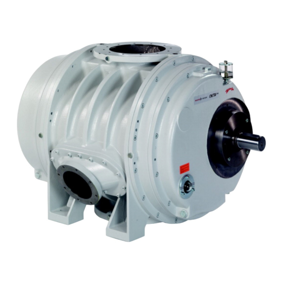
Product description Pump types Pump type Pump designs Standard version Pump in standard version: ● Standard motor ● Connection flanges are designed as ISO, DIN or ANSI flanges ● Connections for sealing gas inlet ● Shaft sealed with radial shaft seal ring (RSSR) ●... - Page 10 335 Lubricant filler screw (2x) version with axial face seal Fore-vacuum 335.1)Lubricant drain screw (2x) flange Sealing gas connection Fig. 3: Roots pump Okta 4000 G Vacuum flange Fore-vacuum flange Cooling gas connection Suction chamber Gas cooler Main rotor Slave rotor Fig.
-
Page 11: Range Of Application
Product description Cooling (option) The (usually) water-cooled gas cooler must be positioned at the gas outlet port of the pump. In addition, the pump temperature needs to be monitored by a thermostat, which switches off the pump, if the preset temperature limit is exceeded (e.g. due to failure of the cooling water system). -
Page 12: Installation
Installation Installation CAUTION Loss of stability! Risk of injury due to the pump's tipping towards motor as long as the pump is not fas- tened to the base. Secure pump with suitable lifting device on motor side. Wear safety shoes with steel toe cap according to directive EN 347. Setting up the pump When installing the pump, observe the following conditions: ... - Page 13 Installation NOTICE Use permitted lubricants only! If lubricants are used that have not been approved by Pfeiffer Vacuum, only a limited warranty shall exist. Attainment of the product-specific performance data cannot be guaranteed in such cases. Use other application-specific lubricants only after first consulting with Pfeiffer Vacu- Filling with lubricant ...
- Page 14 Installation Adding sealant for When using a mechanical seal (optional), a cooling of the sealing surfaces is required. The sealant reservoir needs to be attached above the shaft feedthrough on the outside the mechanical seal of the pump, on the base frame or in a different suitable location depending on the actual (versions with MS conditions.
-
Page 15: Connecting The Vacuum Side
Installation Connecting the vacuum side WARNING Exposed, rotating rolling pistons! Fingers and hands can become crushed when the intake flange is open. Keep all body parts out of operating range of the rolling pistons. Use a wooden handle to rotate the rolling pistons during cleaning. ... -
Page 16: Connecting A Gas Cooler (Optional)
These can be adapted by the operator or ordered from Pfeiffer Vacuum. The dimensioning of the cold gas recirculation line (7.1) should also be matched to the gas cooler and the pump. - Page 17 Installation Requirements for the cooling water Min. oxygen content 4 mg/kg Max. chloride content 100 mg/kg Max. carbonate hardness for the water temperatures 15 ... 25 °C 10 ° dH 30 ... 40 °C 6° dH Max. potassium permanganate usage 10 mg/kg pH value 7 ...
-
Page 18: Temperature Monitoring (Option)
Installation Installing the pres- The pumps can be effectively protected against failure of the cooling water system by installing a cooling water pressure monitor. sure monitor (op- tional) Assembly Refer to the installation instructions provided by the manufacturer. Set switching pressures; set pressure as excess gauge pressure relative to atmo- spheric pressure: –... -
Page 19: Connecting To The Mains Power Supply
Installation Connecting to the mains power supply The pumps are supplied with three-phase motors for different voltages and frequencies. The applicable motor type is shown on its rating plate. DANGER Voltage-bearing elements Danger to life from electric shock. The electrical connection can be carried out only by trained and authorised electri- cians. - Page 20 Installation W2 U2 U1 V1 Fig. 10: Motor coil and connecting plate of Star Connection (for high voltage) Visual inspection of the direction of rotation Check the direction of rotation of the pump after switching on for the first time: –...
- Page 21 Installation Motor protection With PTC temperature sensors (3PTC) Pump motors equipped with PTC temperature sensors (3PTC) in the stator windings can be connected to a PTC resistor tripping device for protection against overload. Other ap- proved motor temperature monitoring can be used also by the operator. Tripping devices store the shutdown event and need to be manually switched back on again via the integrated RESET button or via the external RESET S3.
-
Page 22: Connecting Accessories
Installation Connecting accessories The following accessories are not included in the delivery, and can be ordered separate- Sealing gas connec- The evacuation of high-boiling media (e.g. solvents) can be damaging to the lubricant. Damage can be avoided by letting in sealing gas (process-specifically) into the shaft pas- tion sageways between the operating chamber and the gear chamber. -
Page 23: Operation
Operation Operation Before switching on Check lubricant levels at both sight glasses and at the oiler as well. Protect the pump sufficiently from taking in contaminants by means of suitable precau- tions (e.g. protective strainer); if necessary, check lubricant regularly or replace at shorter intervals. - Page 24 Proportion of sealing gas in the operating gas flow (0.01 A 0.08) Rated suction capacity of the Roots pump [m Example for Okta 4000 G with 50 hPa intake pressure and 8% sealing gas quantity: 4860 · 50 · 0,08 1013 = 19,2 Nm This applies to exhaust pressures >...
-
Page 25: Switching Off
Operation Pump type max. flushing quantity Okta 8000 G 2.0 l/min Okta 3000/4000 G 1.5 l/min Okta 1000/1500 G 1.0 l/min Okta 500 G 0.5 l/min NOTICE High pressures are generated in the working chamber of the pump! Exceeding the specified flushing quantities can lead to destruction of the pump. ... - Page 26 Operation Switch off the pump. Venting should be performed via the suction side, do not ventilate vacuum chambers through the pump. Stop flushing gas feed. Stop cooling water supply. Switching back on After switching off the pump it can be switched back on again within 5 minutes. If you wait any longer then leave the pump to cool to ambient temperature before switching back on again.
-
Page 27: Maintenance
Maintenance Maintenance Precautions WARNING Exposed, rotating rolling pistons! Fingers and hands can become crushed when the intake flange is open. Keep all body parts out of operating range of the rolling pistons. Use a wooden handle to rotate the rolling pistons during cleaning. WARNING Pump parts may be contaminated from pumped media! Danger of poisoning due to contact with harmful substances. -
Page 28: Changing The Lubricant
Checklist for inspec- Certain maintenance and overhaul work should only be performed by Pfeiffer Vacuum Service (PV). Pfeiffer Vacuum will be released from all warranty and liability claims if the tion, maintenance required, below listed, intervals are exceeded or maintenance or overhaul procedures and overhaul are not performed properly. - Page 29 Fill with new lubricant and check fill level. Screw in lubricant filler screws 335. Request safety data sheets for operating fluids and lubricants from Pfeiffer Vacuum or download at www.pfeiffer-vacuum.com. Dispose of operating fluid according to the local regulations. Change sealing oil It is recommended that the sealing oil should be changed on an annual basis.
-
Page 30: Cleaning The Suction Chamber
Maintenance Cleaning the suction chamber WARNING Exposed, rotating rolling pistons! Fingers and hands can become crushed when the intake flange is open. Keep all body parts out of operating range of the rolling pistons. Use a wooden handle to rotate the rolling pistons during cleaning. ... -
Page 31: Decommissioning
Replace the lubricant. Replace bearings. Follow the maintenance instructions and inform Pfeiffer Vacuum. Check pump for visible damage and only start up if it is in the correct condition. If drying pearls were inserted then they should be removed now. -
Page 32: Malfunctions
NOTICE Service work should be carried out by a qualified person only! Pfeiffer Vacuum is not liable for any damage to the pump resulting from work carried out improperly. Take advantage of our service training programs; additional information at www.pfei- ffer-vacuum.com. -
Page 33: Service
The following steps are necessary to ensure a fast, smooth servicing process: Download the forms "Service Request" and "Declaration on Contamination". Fill out the "Service Request" form and send it by fax or e-mail to your Pfeiffer Vacuum service address. -
Page 34: Spare Parts
Please state all information on the rating plate when ordering spare parts. Other spare parts than those described in this manual must not be used without the agreement of Pfeiffer Vacuum. Set of seals for pumps with mechanical sealant (mechanical seal separately) This set of seals includes all of the seal parts such as O-rings, flat seals and square washers. -
Page 35: Accessories
Okta 4000 G Splinter shield for Okta 4000/4000 M/4000 G/6000/6000 M PP 031 136 -X Further detailed accessories are contained in the Pfeiffer Vacuum printed or Online Cat- alogue. 12.1 Documentation for accessories Depending on the pump version, supplementary information may be required for safe... -
Page 36: Technical Data
1.33 0.133 78.9 1.32 atm·cm 1.01 0.101 59.8 0.76 13.2 Technical data Okta 4000 G Parameter Okta 4000 G Flange (in) DN 250 ISO-F Flange (out) DN 250 ISO-F Cooling gas connection DN 160 ISO-F Nominal pumping speed 2300-6900 m... - Page 37 Außen-/ Ø 311,6 ø 241,3 ø depth Tiefe/ 4 mm ANSI, 10" A ( 1 : 10 ) mit Rille/ with groove ANSI, 10" ø 7/8-9 UNC 7/8-9 UNC ø 406,4 ø ø ø 406,4 Fig. 16: Okta 4000 G...
- Page 38 ● Restriction of the use of certain Hazardous Substances 2011/65/EU The agent responsible for compiling the technical documentation is Mr. Sebastian Ober- beck, Pfeiffer Vacuum GmbH, Berliner Straße 43, 35614 Aßlar. Okta 4000 G Harmonised standards and national standards and specifications which have been ap-...
- Page 39 VACUUM SOLUTIONS FROM A SINGLE SOURCE Pfeiffer Vacuum stands for innovative and custom vacuum solutions worldwide, technological perfection, competent advice and reliable service. COMPLETE RANGE OF PRODUCTS From a single component to complex systems: We are the only supplier of vacuum technology that provides a complete product portfolio.
Need help?
Do you have a question about the OKTA 4000 G and is the answer not in the manual?
Questions and answers