
Subscribe to Our Youtube Channel
Related Manuals for Toa DT-940UL


Summary of Contents for Toa DT-940UL
- Page 1 OPERATING INSTRUCTIONS AM/FM TUNER DT-940 Thank you for purchasing TOA’s AM/FM Tuner. Please carefully follow the instructions in this manual to ensure long, trouble-free use of your equipment.
-
Page 2: Table Of Contents
TABLE OF CONTENTS 1. IMPORTANT SAFETY INSTRUCTIONS ..........3 2. SAFETY PRECAUTIONS ................3 3. INFORMATION TO THE USER ..............4 4. GENERAL DESCRIPTION ................5 5. NOMENCLATURE AND FUNCTIONS ..........5 Front ..........................5 Rear ..........................6 6. RADIO RECEPTION .................. -
Page 3: Important Safety Instructions
• Should the following irregularity be found during use, immediately switch off the power, disconnect the power supply plug from the AC outlet and contact your nearest TOA dealer. Make no further attempt to operate the unit in this condition as this may cause fire or electric shock. -
Page 4: Information To The User
• Use the dedicated AC adapter for the unit. Note that the use of other adapter may cause a fire. • Contact your TOA dealer as to the cleaning. If dust is allowed to accumulate in the unit over a long period of time, a fire or damage to the unit may result. -
Page 5: General Description
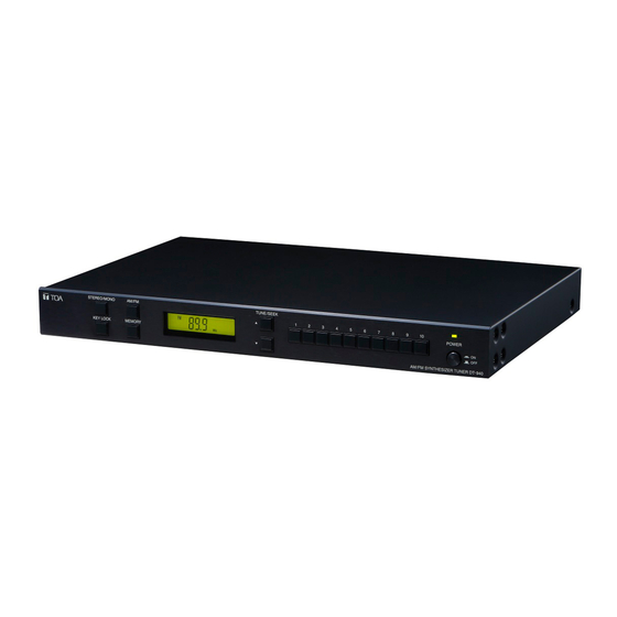
4. GENERAL DESCRIPTION The DT-940 is an AM/FM radio tuner. 20 receiving channels each of AM and FM broadcasts can be stored in memory, which can be recalled by one- touch key operation. The unit can be mounted on an EIA equipment rack using the optional MB-15B Rack Mounting Bracket. 5. -
Page 6: Rear
[Rear] 12 13 10. Functional ground terminal 15. Monaural output terminals Hum noise may be generated when external Provide monaural audio output of received radio equipment is connected to the unit. Connecting programs. this terminal to the functional ground terminal Connect the output cable to the "H"... -
Page 7: Radio Reception
6. RADIO RECEPTION The following 2 modes are available for receiving the desired frequency. (1) Auto tuning mode: Automatically detects and selects the frequency. (2) Manual tuning mode: The frequency is changed in specified steps, and selected manually. [Keys used for operation] Stereo/Monaural selector key LCD indicator Tuning keys... -
Page 8: Manual Tuning Mode
6.2. Manual Tuning Mode Step 1. Press the AM/FM Band selector key to select either AM or FM broadcast. The selected band is displayed on the screen. Step 2. Press the Tuning Key ( ) several times to select the desired receiving frequency. Each time the key is pressed, the frequency increases by 10 kHz for AM broadcasts or by 100 kHz for FM broadcasts. -
Page 9: Manual Memory Preset
7.1. Manual Memory Preset Step 1. Tune in the desired frequency. Use Auto tuning or Manual tuning method for broadcast reception. (See p. 7.) Step 2. Press the Memory key. The "CH – –" indication flashes on the LCD indicator. Step 3. -
Page 10: Recalling The Preset Frequency
8. RECALLING THE PRESET FREQUENCY [Keys used for operation] AM/FM band selector key LCD indicator Preset memory enter keys Stereo broadcast receiving indication Receiving band (No indication while in Monaural broadcast receiving mode) Receiving frequency Preset channel number Step 1. Press the AM/FM Band selector key to select either AM or FM broadcast. The selected band is displayed on the LCD indicator. -
Page 11: Key Locking
9. KEY LOCKING All key operations except the Power switch and the Key lock key can be disabled by pressing the Key lock key. Key lock status is retained even when the unit’s power is switched off. Key lock key LCD indicator Key lock status indication 9.1. -
Page 12: Am Antenna Connections
10.2. AM Antenna Connections 10.2.1. When using the supplied AM loop antenna Connect the supplied AM loop antenna to the AM antenna terminals. Use the supplied AM loop antenna to receive broadcasts if satisfactory reception can be obtained. Adjust the loop antenna’s position for the best possible reception while listening to AM broadcasts. AM loop antenna setup Finish DT-940 rear... - Page 13 [When using a coaxial cable] Use the RG-59/U or RG-6/U coaxial cable. Treat the coaxial cable end, then connect it to the right side of the AM antenna terminals viewed from the unit’s rear panel. Coaxial cable clamp AM antenna terminal (right side) Coaxial cable DT-940 rear AM antenna...
-
Page 14: Fm Antenna Connections
10.3. FM Antenna Connections Connect the supplied FM wire antenna or a commercially available FM antenna to the FM antenna terminal. Cord clamp DT-940 rear Commercial FM antenna F-type terminal F-type Cord clamp connector Note The antennas can receive radio signals at the highest level from the direction indicated by the arrow. -
Page 15: Rack Mounting
Rack mounting screw 5 x 12 (supplied with the MB-15B) CAUTION MB-15B (option) Fiber washer for M5 The rack mounting screws (5 x 12) are (supplied with the MB-15B) dedicated for the TOA equipment racks. Do not use them for other racks. -
Page 16: Specifications
FM wire antenna* ........1 For indoor use only, 135 x 125 mm (5.31" x 4.92"), leadwire: 1.2 m (3.94 ft) For indoor use only, element length: 2.2 m (7.22 ft) • Optional product Rack mounting bracket: MB-15B URL: https://www.toa.jp/ 133-07-00121-02...
Need help?
Do you have a question about the DT-940UL and is the answer not in the manual?
Questions and answers