Toa WT-5800 Operating Instructions Manual
Wireless tuners
Hide thumbs
Also See for WT-5800:
- Specifications (4 pages) ,
- Operating instructions manual (64 pages) ,
- Operating instructions manual (60 pages)
Table of Contents
Advertisement
Quick Links
WIRELESS TUNERS
A F
P E
A K
B T
T
A N
A
TABLE OF CONTENTS
1. SAFETY PRECAUTIONS .......................... 2
2. GENERAL DESCRIPTION ........................ 3
3. FEATURES ................................................ 3
4. HANDLING PRECAUTIONS ..................... 4
Front ........................................................... 4
Rear ............................................................ 5
6.1. Basic Operation ................................... 5
6.2. Function Settings ................................. 6
Thank you for purchasing TOA's Wireless Tuner.
Please carefully follow the instructions in this manual to ensure long, trouble-free use of your equipment.
T
B
D I V
E R
S I T
U H
F W
Y W
I R E
I R E
L E
L E
S S
S S
T U
N E
R W
T - 5
8 0 0
V O
L
1 0
OPERATING INSTRUCTIONS
U P
S E
T
P O
W E
R
D O
W
WITH INTERFERENCE .............................. 9
8. CONNECTION EXAMPLES ..................... 10
9. RACK MOUNTING ................................... 11
10. SPECIFICATIONS .................................... 12
Accessories ............................................... 12
Optional products ...................................... 12
WT-5800
WT-5805
Advertisement
Table of Contents

Related Manuals for Toa WT-5800


Summary of Contents for Toa WT-5800
-
Page 1: Table Of Contents
Rear ............5 Optional products ........12 6. OPERATION 6.1. Basic Operation ........5 6.2. Function Settings ......... 6 Thank you for purchasing TOA's Wireless Tuner. Please carefully follow the instructions in this manual to ensure long, trouble-free use of your equipment. -
Page 2: Safety Precautions
• Should the following irregularity be found during use, immediately switch off the power, disconnect the power supply plug from the AC outlet and contact your nearest TOA dealer. Make no further attempt to operate the unit in this condition as this may cause fire or electric shock. -
Page 3: General Description
2. GENERAL DESCRIPTION The WT-5800/5805 Wireless Tuner is designed for use on the UHF band, and suitable for vocal or speech reinforcement applications. It features a compander circuit which minimizes the influence of ambient noise. -
Page 4: Handling Precautions
• Antenna distribution outputs (WT-5800 only) and audio cascade inputs facilitate connection of another unit to build a dual-channel system. • Compact and high reliability 4. HANDLING PRECAUTIONS • Make sure that the power switch is switched OFF after use. -
Page 5: Rear
45° angle outwards –20 dB*/– 60 dB* selectable, unbalanced, phone from a vertical line. jack. 10. Antenna distribution output A, B (WT-5800 only) 15. AF output level selector 75 Ω, BNC Sets the output level from the AF outputs by selecting either MIC (–... -
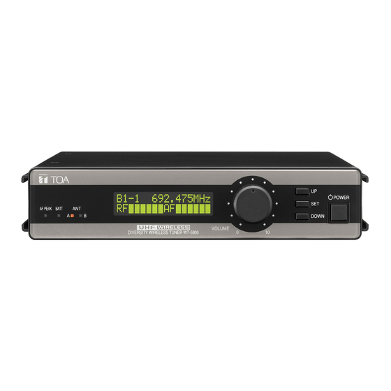
Page 6: Function Settings
POWER AF PEAK BTT DOWN UHF WIRELESS VOLUME DIVERSITY WIRELESS TUNER WT-5800 Set key Down key Setting items displayed on the LCD screen The display cycles through the indications "SET CHANNEL," "SET BANK," "SET SQ LEVEL," "SET LCD POWER," CHANNEL CHECK," "RF CHECK," "About Model" and "Exit" with each depression of the Up key, or the Down key for the reverse action. - Page 7 6.2.3. Squelch level setting The WT-5800/5805 tuner has the squelch function that virtually eliminates ambient noise and unwanted audio signals from other wireless microphone systems by silencing the output when the signal received is lower than a certain level of signal strength. This strength level can be varied by means of the squelch control.
- Page 8 6.2.5. Channel detection Step 1. Press the Set key for over a second to place the unit in setting mode. Step 2. Select the setting item "CHANNEL CHECK" with the Up or Down key. Step 3. Press the Set key. Channel detection begins, and an idle channel number with frequency is displayed on the screen.
-
Page 9: How To Check And Deal With Interference
7. HOW TO CHECK AND DEAL WITH INTERFERENCE [Order of Actions (Action Flowchart)] Place unit in RF check mode and check Refer to p. 8 "6.2.6. RF check." signal condition of the channel. [No] Use as is. interference? [Yes] Change bank/channel numbers to those of Refer to p. -
Page 10: Connection Examples
Balanced To amplifier's MIC or LINE input Unbalanced [Example 2] Wall-mounted wireless antenna Wall-mounted wireless antenna Accessory Accessory YW-4500 (optional) YW-4500 (optional) 1st WT-5800 unit ANT B DC IN OUTPUT 600 MIX IN ANT A BALANCED UNBALANCED UNBALANCED -20dBV LEVEL... -
Page 11: Rack Mounting
9. RACK MOUNTING • When mounting one WT-5800/5805 unit, use an optional mounting kit MB-WT3. Bracket B * WT-5800/5805 D IV S IT IR E IR E T -5 8 0 0 Fiber washer * (for M5) Rack mounting screw *... -
Page 12: Specifications
Note: The design and specifications are subject to change without notice for improvement. • Accessories AC-DC adapter ........... 1 • Optional products Mounting bracket kit: MB-WT3 (for rack mounting one WT-5800/5805 unit) MB-WT4 (for rack mounting two WT-5800/5805 units) URL: http://www.toa.jp/ 133-07-268-20...
Need help?
Do you have a question about the WT-5800 and is the answer not in the manual?
Questions and answers