
Subscribe to Our Youtube Channel
Related Manuals for Danfoss VLZ065


Summary of Contents for Danfoss VLZ065
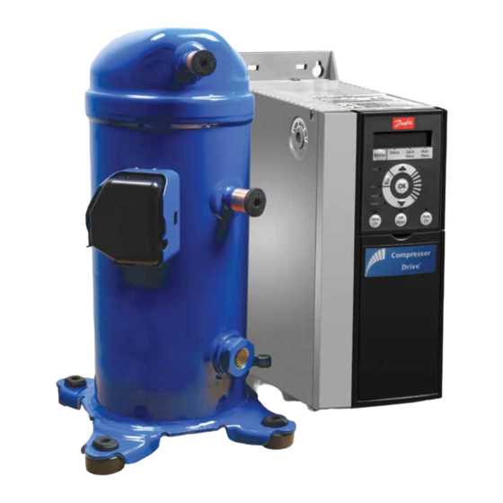
- Page 1 Application guidelines Danfoss scroll compressors VLZ065 version B Single R404A/R448A/R449A CDS drive http://cc.danfoss.com...
-
Page 3: Table Of Contents
Content General Information ........ 4 Manage off cycle migration ....28 Requirement .............28 System evaluation ..........28 PRODUCT INFORMATION ......5 Manage operating envelope ....29 Features............. 5 Requirement .............29 System evaluation ..........30 How do IDVs work? ........... 5 Manage speed limit ........ 34 Compressor model designation ..... -
Page 4: General Information
Related instructions are guidelines, please contact Danfoss Technical highlighted with the following icons: Support. In any case, Danfoss accepts no liability as a result of the improper integration This icon indicates instructions to avoid of the compressor into the unit by the system safety risk. -
Page 5: Product Information
POE 46 lubricant ensures better lubrication and efficiency Linear control oil pump How do IDVs work? Danfoss Intermediate Discharge Valves (IDVs) are located close to the discharge side of the compressor. They reduce excessive compression of refrigerant under part-load conditions while maintaining the same cooling capacity. -
Page 6: Compressor Model Designation
Compressor model designation Nomenclature Compressor nomenclature Variable speed With CDS drive Equipment version Family 9: brazed connections, single version Scroll (refrigeration) D: brazed connections, uni ed version Oil sight glass Oil level switch Lubricant Single version Threaded None POE46(RL46HB) lubricant Uni ed version Threaded Threaded... -
Page 7: Technical Specifications
Technical specifications Compressor size To have the optimum compressor selection, Detailed performances can be found in select a compressor size which achieves the datasheets and in selection programs. peak load system cooling capacity demand at its maximum speed. Frequency converter Different frequency converter variants are 3. - Page 8 (cm³/rev) (cu.in/rev) (m³/h) (cu.ft/h) (m³/h) (cu.ft/h) (m³/h) (cu.ft/h) (m³/h) (cu.ft/h) (oz) (kg) (lbs) VLZ065 65.1 11.7 14.1 25.8 1.57 Frequency converter specifications Mains supply voltage T4: 380 - 480 V ±10% (3-phase) Supply frequency 50 / 60 Hz Output voltage...
- Page 9 R - External Load / Relay Oil level sensor is a special component which assembles on variable speed compressor. The oil level sensor prism is fixed on the compressor, the electrical part and the pre-wired connectors are ordered by accessory kit. VLZ065 AB444226142054en-000101...
-
Page 10: Dimensions
Recommended torque for mounting bolts: 11 Nm (±1 Nm) Earth grounding Version Compressor model Outline drawing number (mm) (inch) (mm) (inch) (mm) (inch) (mm) (inch) (mm) (inch) (mm) (inch) Single VLZ065 183.5 7.22 17.17 15.87 10.28 190.5 190.5 8590007 Unified VLZ065 183.5... - Page 11 Dimensions Connection Details VLZ065 single version Suction connection Brazed 7/8" Discharge connection Brazed 3/4" Oil sight glass Threaded (1"1/8 – 18 UNF) Oil equalization connection Shrader Male 1/4" Flare incorporating a Schrader valve 1) VLZ compressors single versions come 2) Schrader: The oil fill connection and equipped with a threaded oil sight glass with gauge port is a 1/4"...
- Page 12 [H x W x L] Drive below Bracket supplied en‐ closure (mm2) (inch) (inch) 1pcs, Φ2-11 402 × 150 × 255 T4: 380-480/3/50-60 VLZ065 1pcs, Φ3-18 (15.8 × 5.9 × 10) 1pcs, Φ6-23 Drive outline dimensions Decoupling plate CC-000089 Enclosure Height Width Depth Mounting hole Max.
-
Page 13: Electrical Data, Connections And Wiring
Compressor rated voltage (V) Model RW(Ω) at 20°C line to line Max Operating Current (A) VLZ065-G 0.177Ω±7% RW: Winding resistance per winding, measured at motor terminals MOC (Max Operating Max. operating current is the max. continuous MOC is tested at max. load condition with... - Page 14 Electrical data, connections and wiring Fuses Danfoss recommends using the fuses listed For circuit breakers, Moeller types have been below to protect service personnel and property tested and are recommended. in case of component break-down in the frequency converter. Recommended cir‐...
-
Page 15: Protection
Electrical data, connections and wiring Phase sequence and The compressor will only operate properly can operate in a reverse rotation. This results in reverse rotation in a single direction. If electrical connections excessive noise, no pressure differential between protection are done correctly between the drive and the suction and discharge, and suction line warming compressor terminals (compressor T1/T2/T3 and rather than immediate cooling. -
Page 16: Approval And Certificates
VLZ code G (European Directive) EMC Class A Group 1 VLZ compressor and drive package 2014/30/EU Low voltage directive Products VLZ065 2014/35/EU Declaration of conformity ref. Contact Danfoss Low voltage directive 2014/35/EU Internal free volume Products Internal free volume at LP side without oil (lite/cu.inch) VLZ065 4.7/287... -
Page 17: System Design
Drive installation Direct and indirect IP20 drives are intended for indoor or cabinet It is recommended to place drive at least 30cm exposure of drive to water mounting. Application example: drive fitted in from ground to protect against floods. a machine room, basement or in an electrical cabinet together with other electric / electronic components such as the unit controller or contactors. -
Page 18: Ambient Temperature
Drive installation Ambient temperature The maximum ambient temperature for the drive The drive could operate lower to -10C with is 52°C. proper operation, such as inside the cabinet, install the space heater. LCP operating Make sure that the clearance limits described temperature is -10 ~ 50 °C. -
Page 19: Emc Installation
EMC installation Frequency converter (and other electrical The EMC product standard for frequency devices) generate electronic or magnetic fields converters defines 4 categories (C1, C2, C3, and that may interfere with their environment. The C4) with specified requirements for emission and electromagnetic compatibility (EMC) of these immunity. -
Page 20: Unit Architecture
10V is control, oil return management and short cycling maximum compressor speed. protection. Below is the Danfoss proposed system configuration and wiring. Unit controller Fuses or CDS 803 circuit breaker 12 + 24V CC (80mA max.) -
Page 21: Piping Design
Piping Design General requirements Proper piping practices should be employed to: 2. Avoid condensed liquid refrigerant from draining back to the compressor when stopped 1. Ensure adequate oil return, even under (discharge piping upper loop). For validation minimum load conditions (refrigerant speed, tests see section “Manage off cycle migration”. -
Page 22: Design Compressor Mounting
Design compressor mounting General requirements Compressors used in single applications must be During operation, the maximum inclination from mounted with flexible grommets. the vertical plane must not exceed 7 degrees. Single requirements All compressors are delivered with four rubber grommets and metal sleeves. Compressors Not supplied with grommet must always be mounted with these grommets. -
Page 23: Manage Oil In The Circuit
Manage oil in the circuit Requirement Oil level must be visible or full in the sight For VLZ, an oil separator is mandatory to use to glass when the compressor is running and when guarantee oil return. all compressors of the circuit are stopped. System evaluation Single compressor 1. -
Page 24: Manage Sound And Vibration
Acoustic hoods are available from at shut down and should be less than 3 seconds. Danfoss as accessories. Refer to the table above This phenomenon has no impact on compressor for sound levels, attenuation and code numbers. -
Page 25: Mechanical Vibrations
Mitigations methods: If some resonant frequencies generate high 1. Danfoss VLZ scroll compressors are designed to piping vibration, problem can be solved by produce minimal vibration during operations. To increasing piping stiffness with brackets or ensure minimum vibrations transmission to the changing layout. -
Page 26: Manage Superheat
Manage superheat During normal operation, refrigerant enters Liquid flood back can cause oil dilution and, in the compressor as a superheated vapor. Liquid extreme situations lead to liquid slugging that flood back occurs when a part of the refrigerant can damage compression parts. entering the compressor is still in liquid state. -
Page 27: Test, Criteria And Solutions
Evaporating Temperature (°F) Acceptable Acceptable Unacceptable Unacceptable Evaporating Temperature (°C) Evaporating Temperature (°C) Danfoss Danfoss OE-000064 OE-000065 Oil temperature sensor must be placed between oil sight glass and compressor baseplate. Some thermal paste shall be used to improve the conductivity. The sensor must also be correctly thermally insulated from the ambiance. -
Page 28: Manage Off Cycle Migration
***Pump-down cycle Crankcase heater accessories are available from By decreasing pressure in the sump, pump down: Danfoss (see section “Accessories”). • Evacuates refrigerant from oi.l • Set the sump saturating pressure much lower than ambiance temperature and due to that, avoid refrigerant condensation in the compressor. -
Page 29: Manage Operating Envelope
135°C (275°F). Steady-state operation guarantees reliable operations of the compressor envelope is valid for a suction superheat above for steady-state operation. 10K. VLZ065 operating map - R404A Single envelope control Evaporating temperature (°F) 3000-6600 rpm 1800-6600 rpm SH10K RGT=20°C... -
Page 30: System Evaluation
Manage operating envelope System evaluation VLZ drive can only protect the compressor from permanently checking that the compressor is over current. To manage operating envelop, an running within the defined envelope. advanced envelope protection principle needs to be used with variable speed compressors. When compressor reach a limit, controller can act This solution offers much better protection than on different parameter to avoid unit tripping. - Page 31 Manage operating envelope Multiple envelope control: Speed range <3000 allowed Controller needs to manage speed limitation Below 2400RPM oil boost function is disabled according to operating conditions. by default but could be enabled by OEM (more details “Oil management logic”) Protection required See “Test, criteria and solutions”...
- Page 32 Manage operating envelope Discharge temperature Discharge gas temperature (DGT) protection below, which illustrate where DGT protection is protection is required if the high and low pressure switch required (Ex. 1) and where it is not (Ex. 2). Please settings do not protect the compressor against notice the envelope boundaries change based operations beyond its specific application on different speed limits.
- Page 33 Manage operating envelope MOP (Max operating In steady state, it is essential to prevent the limit we have on our VS operating envelope. pressure) control compressor running when evaporating T° is higher than the specified envelope. Operating Regardless of EXV or TXV, customer needs to the compressor higher than maximum qualify the expansion device.
-
Page 34: Manage Speed Limit
Customer could change the default values if the reliability and must be respected. In drive control changes have been qualified by OEM. logic, default setting values have been qualified by Danfoss. Start/Stop/Ramp setting 6600 Ramp 1 ramp down time 3-42... -
Page 35: Control Logic
Danfoss recommends the use of ETS products. Ramp-up and ramp-down Ramp-down of the EXV must be longer than the settings, of both EXV and compressor, must be ramp-down of the compressor, also to avoid low done with great care. -
Page 36: Pump-Down Logic Recommendations
Control logic Pump-down logic Pump down is initiated prior to shutting or electronic expansion valve remains closed. recommendations down the last compressor on the circuit by • Continuous pump-down: Compressor de-energizing a liquid line solenoid valve restarts automatically when suction pressure or closing electronic expansion valve. -
Page 37: Oil Boost Controlled By Optical Oil Level Sensor
Control logic Drive parameters Description Default Range “28.10” Oil return management Enables/disables Oil Return Management Enable On / Off “28.11” Low speed running Threshold for boost decision 120 min 1-1440 min “28.12” Fixed boost interval Maximum time between oil return boosts 1-168h “28.13”... - Page 38 Control logic The oil management control logic must include 2 steps. CC-000103 Less than every 20min (TD2*) Low oil level Max 45 >5 sec sec (TD1*) Normal Oil level not Protection Low oil level Boost operation recovered Step 1 Step 2 Step 1 (oil boost) if oil level sensor detects low TD2 is the minimum interval between two step level for more than 5 seconds, oil is trapped in...
- Page 39 Control logic Step 2 Protection function description Cancel condition: Manual Reset Stop the compressor to prevent short of oil running. Control sequence: Stop VS compressor Enter condition: Low oil level in VS compressor detected by oil level sensor. • Reset t1 •...
-
Page 40: Reduce Moisture In The System
To achieve this requirement, a properly sized For new installations with VLZ compressors with and type of drier is required. Important selection POE oil, Danfoss recommends using the Danfoss criteria include: DML (100% molecular sieve) solid core filter drier. • driers water content capacity, •... -
Page 41: Integration Into Systems
• Remove the nitrogen holding charge via the suction Schrader valve to avoid an oil mist blow out. Handling Each Danfoss VLZ scroll compressor is • The use of lifting hooks closed with a clasp is equipped with one lift ring on the top shell. recommended. -
Page 42: Piping Assembly
Assembly line procedure Piping assembly Good practices for piping assembly is a pre-requisite to ensure compressor service life (system cleanliness, brazing procedure...) System cleanliness Circuit contamination possible cause Requirement Brazing and welding oxides During brazing, flow nitrogen through the system Filings and particles from the removal of burrs in Remove any particles and burrs generated by tube pipework... -
Page 43: Vacuum Evacuation And Moisture Removal
Assembly line procedure Vacuum evacuation and moisture removal Requirements: Recommendations: • Never use the compressor to evacuate the • Energized heaters improve moisture removal. system. • Alternate vacuum phases and break vacuum. • Connect a vacuum pump to both the LP and HP with Nitrogen to improve moisture removal. -
Page 44: Commissioning
See news bulletin “Lubricants sight glass. filling in instructions for Danfoss Commercial Compressors” TI 2-025-0402. The presence of foam filling in the sight glass indicates large concentration of refrigerant in the oil and / or presence of liquid returning to the compressor. -
Page 45: Troubleshooting
Troubleshooting Check alarm # Over current Start failure Speed limit Compressor failure Replace compressor only and return it for inspection if under warranty Check alarm # Motor phase Motor phase Motor phase U missing V missing M missing Most probably neither a drive or compressor failure Check the motor... - Page 46 Troubleshooting Check alarm # #A45 Earth Earth (ground) fault (ground) fault Power OFF the unit Disconnect power cable at compressor electrical box Perform an insulation resistance test on the compressor with 'megger' tester. 500V # resistance < 500 K # resistance > 500 K Replace compressor and return it for Replace drive and return it for inspection inspection if under warranty...
-
Page 47: Dismantle And Disposal
Dismantle and disposal Danfoss recommends that compressors and compressor oil should be recycled by a suitable company at its site. AB444226142054en-000101... -
Page 48: Ordering Information
(mm) (inch) (mm) (inch) (mm) (inch) (kg) (lb) VLZ065 20.6 11.5 11.3 Compressor Industrial pack Compressors are not packed individually but are ordered in quantities of full pallets only, multiples shipped all together on one pallet. They can be of 12 compressors, according to below table. -
Page 49: Ordering Codes
Ordering codes Compressor code numbers Danfoss scroll compressors VLZ can be ordered can be ordered in single packs. Please use the in either industrial packs or in single packs. Drive code numbers from below tables for ordering. Single pack 380-480V/3ph/50&60Hz... -
Page 50: Accessories
2 rotolock nuts 1"1/4 with sleeves and gaskets VLZ065 Multipack Rotolock adapter Code n° Description Application Packaging Pack size 120Z0367 Adaptor (1-1/4" ~ 7/8") VLZ065 suction Multipack 120Z0366 Adaptor (1-1/4" ~ 3/4") VLZ065 discharge Multipack Mounting kits Code No Description Application... - Page 51 Oil level switch-electrical part(230V AC) with relay* All models Single pack * Danfoss does not provide c connector without cable, please order 2m and 8m pre-wired connectors in.the table of Connector for oil level sensor Connector for oil level sensor...
- Page 52 Accessories Decoupling plate Frame Compressor Decoupling plate packaging Pack size VLZ065 120Z0583 Single pack AB444226142054en-000101...
- Page 53 AB444226142054en-000101...
- Page 54 Danfoss Light Commercial Refrigeration Compressors Our products can be found in a variety of applications such as rooftops, chillers, residential air conditioners, heat pumps, cold-rooms, supermarkets, milk tank cooling and industrial cooling processes. © Danfoss | DCS (CC) | 2023.05 AB444226142054en-000101...
Need help?
Do you have a question about the VLZ065 and is the answer not in the manual?
Questions and answers