Table of Contents
Advertisement
Quick Links
IM10056
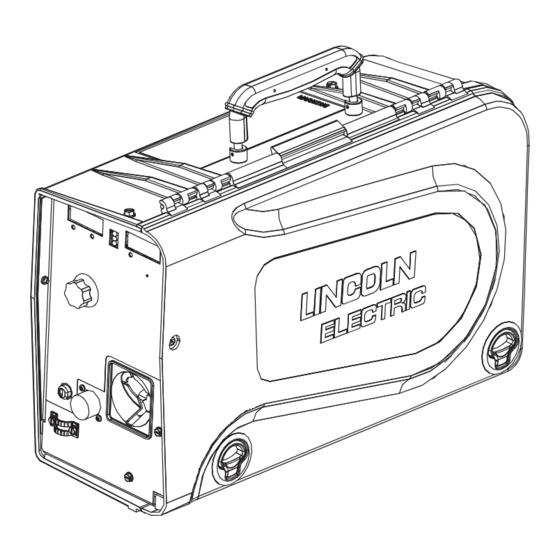
LN™- 25 PIPE
April, 2011
For use with machines having Code Number: 11693
Safety Depends on You
Lincoln arc welding and cutting
equipment is designed and built
with safety in mind. However, your
overall safety can be increased by
proper installation ... and thoughtful
operation on your part. DO NOT
INSTALL, OPERATE OR REPAIR
THIS EQUIPMENT WITHOUT
READING THIS MANUAL AND
THE SAFETY PRECAUTIONS
CONTAINED THROUGHOUT.
And, most importantly, think before
you act and be careful.
IP23
IEC 60974-5
OPERATOR'S MANUAL
Copyright © Lincoln Global Inc.
• World's Leader in Welding and Cutting Products •
• Sales and Service through Subsidiaries and Distributors Worldwide •
Cleveland, Ohio 44117-1199 U.S.A. TEL: 216.481.8100 FAX: 216.486.1751 WEB SITE: www.lincolnelectric.com
Advertisement
Table of Contents

Subscribe to Our Youtube Channel
Related Manuals for Lincoln Electric K2614-5


Summary of Contents for Lincoln Electric K2614-5
- Page 1 IM10056 LN™- 25 PIPE April, 2011 For use with machines having Code Number: 11693 Safety Depends on You Lincoln arc welding and cutting equipment is designed and built with safety in mind. However, your overall safety can be increased by proper installation ...
- Page 2 THANK YOU FOR SELECTING A QUALITY PRODUCT BY KEEP YOUR HEAD OUT OF THE FUMES. DON’T get too close to the arc. LINCOLN ELEC TRIC. Use corrective lenses if necessary to stay a reasonable distance away from the arc. READ and obey the Safety Data PLEASE EXAMINE CARTON AND EQUIPMENT FOR Sheet (SDS) and the warning label DAMAGE IMMEDIATELY...
- Page 3 W117.2-1974. A Free copy of “Arc Welding Safety” booklet E205 is available from the Lincoln Electric Company, 2.d. All welders should use the following procedures in order to 22801 St. Clair Avenue, Cleveland, Ohio 44117-1199.
- Page 4 SAFETY ELECTRIC SHOCK ARC RAYS CAN BURN. CAN KILL. 3.a. The electrode and work (or ground) circuits are 4.a. Use a shield with the proper filter and cover plates to protect your electrically “hot” when the welder is on. Do eyes from sparks and the rays of the arc when welding or not touch these “hot”...
- Page 5 SAFETY WELDING AND CUTTING CYLINDER MAY EXPLODE IF SPARKS CAN CAUSE DAMAGED. FIRE OR EXPLOSION. 7.a. Use only compressed gas cylinders containing the correct shielding gas for the process used 6.a. Remove fire hazards from the welding area. If and properly operating regulators designed for this is not possible, cover them to prevent the welding sparks the gas and pressure used.
- Page 6 SAFETY PRÉCAUTIONS DE SÛRETÉ 6. Eloigner les matériaux inflammables ou les recouvrir afin de prévenir tout risque d’incendie dû aux étincelles. Pour votre propre protection lire et observer toutes les instructions et les précautions de sûreté specifiques qui parraissent dans ce 7.
- Page 7 2004/108/EC. It was manufactured in conformity with a national standard that implements a harmonized standard: EN 60974-10 Electromagnetic Compatibility (EMC) Product Standard for Arc Welding Equipment. It is for use with other Lincoln Electric equipment. It is designed for industrial and professional use. Introduction All electrical equipment generates small amounts of electromagnetic emission.
- Page 8 SAFETY Electromagnetic Compatibility (EMC) The size of the surrounding area to be considered will depend on the structure of the building and other activities that are taking place. The surrounding area may extend beyond the boundaries of the premises. Methods of Reducing Emissions Mains Supply Welding equipment should be connected to the mains supply according to the manufacturer’s recommenda- tions.
-
Page 9: Table Of Contents
viii viii TAbLE OF CONTENTS Page –––––––––––––––––––––––––––––––––––––––––––––––––––––––––––––––––––––––––––––––– Installation........................Section A Technical Specifications .......................A-1 Safety Precautions .......................A-2 Location ..........................A-2 High Frequency Protection ....................A-2 Weld cable Sizes ........................A-2 Analog Control Cable ......................A-3 Cable Connections and Control Cable Connector ...............A-4 Shielding Gas Connection ....................A-4 Wire Drive Configuration ......................A-5 Changing The Gun Receiver Bushing ................A-5 Procedure to Install Drive Rolls and Wire Guides ..............A-5... -
Page 10: Installation
INSTALLATION TECHNICAL SPECIFICATIONS – LN™-25 PIPE (K2614-5) INPUT VOLTAGE and CURRENT INPUT VOLTAGE ± 10% INPUT AMPERES 15-110 VDC RATED OUTPUT @ 104°F (40°C) DUTY CYCLE INPUT AMPERES 60% rating GEARING - WIRE FEED SPEED RANGE-WIRE SIzE GMAW FCAW GEARING... -
Page 11: Safety Precautions
INSTALLATION SAFETY PRECAUTIONS The handle of the LN™-25 PIPE is intended for moving the wire feeder about the work place only. WARNING When suspending a wire feeder, insulate the ELECTRIC SHOCK CAN KILL. hanging device from the wire feeder enclosure. • Turn the input power OFF at the HIGH FREQUENCY PROTECTION disconnect switch or fuse box before attempting to connect or... -
Page 12: Shielding Gas Connection
INSTALLATION SHIELDING GAS CONNECTION CAbLE CONNECTIONS WARNING There is one circular connector for the gun trigger on the front of the LN™-25 PIPE. CYLINDER may explode if damaged. • Keep cylinder upright and chained to support. Function Wiring • Keep cylinder away from areas where it may be 5-pin trigger 5 volt supply damaged. -
Page 13: Wire Drive Configuration
INSTALLATION WIRE DRIVE CONFIGURATION 8. Connect the shielding gas hose to the new gun bushing, if required. (See Figure A.2) 9. Rotate the gun bushing until the thumb screw hole CHANGING RECEIVER aligns with the thumb screw hole in the feed plate. bUSHING Slide the gun receiver bushing into the wire drive and verify the thumb screw holes are aligned. -
Page 14: Pressure Arm Adjustment
INSTALLATION 1. Squeeze the release bar on the retaining collar and PRESSURE ARM ADJUSTMENT remove it from the spindle. WARNING 2. Place the spindle adapter on the spindle, aligning the spindle brake pin with the hole in the adapter. ELECTRIC SHOCK can kill. •... -
Page 15: Power Source To Ln™-25 Pipe Connection Diagrams
Engine Driven welder with Wire Feed Module Work Ranger 250 GXT Description Place the power source Remote/Local switch in the K2614-5 LN™-25 PIPE Local position. KP1695-XX KP1696-XX Drive Roll Kit Place CV/CC switch in the feeder in the "CV" position. - Page 16 Remote/Local Switch. (See Figure A.8) FIGURE A.8 LN™-25 PIPE CV-305 Electrode V350-Pro Work clip Work Description Place CV/CC switch in the feeder in the "CV" position. K2614-5 LN™-25 PIPE KP1695-XX KP1696-XX Drive Roll Kit KP1697-XX See Magnum Literature Welding Gun CV power Source K1841...
-
Page 17: Operation
OPERATION SAFETY PRECAUTIONS GRAPHIC SYMbOLS THAT APPEAR ON THIS MACHINE OR IN THIS MANUAL READ AND UNDERSTAND ENTIRE SECTION bEFORE OPERATING MACHINE. INPUT POWER WARNING • ELECTRIC SHOCK CAN KILL. Unless using COLD FEED fea- ture, when feeding with gun trig- ger, the electrode and drive mechanism are always electri- cally energized and could... -
Page 18: Definition Of Welding Terms
OPERATION General Functional Description DEFINITION OF WELDING TERMS The LN™-25 PIPE as designed is a simple, robust feeder. Standard features include a calibrated wire feed speed dial, 2 step/trigger interlock switch, Gas • Wire Feed Speed Purge and Cold Feed. RECOMMENDED PROCESSES •... -
Page 19: Case Front Controls
OPERATION (See Customer Assistance Policy in the front of this WIRE FEED SPEED KNOb Instruction Manual) Wire Feed Speed, CV Operation CASE FRONT CONTROLS When Across the Arc models are operated with CV (See Figure b.1) power sources, the wire feed speed will remain a con- FIGURE b.1 stant value, independent of arc voltage changes, as along as the arc voltage does not drop below the val-... - Page 20 Always use quality electrode, such as L-50 or L-56 Preparation for Amperage Calibration: from Lincoln Electric. Connect the feeder to a power source and grid. POWER-UP SEQUENCE Adjust the power source and grid to the desired amperage.
- Page 21 OPERATION WIRE FEED SPEED UNITS Rotate the WFS knob to To change the wire feed speed units: the right to turn Run-In ON. Rotate the WFS knob to Then rotate the WFS knob left to the 12 o’clock position. “inches/minute” for the wire feed speed units.
- Page 22 OPERATION LEFT DISPLAY SELECTION AMPERAGE CALIbRATION The left display can show either amperage or actual Measurements for adjusting the Amperage calibration WFS during welding. Note that actual WFS is not the must be made before entering the set-up menu. same as preset WFS. For example, the preset WFS may be set to 400 ipm, but the arc voltage is only 15V.
- Page 23 OPERATION INTERNAL CONTROLS FIGURE b.2 ITEM DESCRIPTION 2 Step Trigger Interlock Switch Pressure Adjustment Arm Optional Timer Kit (See Accessories Section) Spool Retainer Spindle Brake Gun Bushing Thumb Screw for securing the welding Gun Socket Head Cap Screw for securing the Gun Bushing Drive Hubs Inlet Wire Guide Cold Feed Pushbutton...
- Page 24 OPERATION INTERNAL CONTROLS DESCRIPTION COLD FEED PUSHbUTTON (See Figure B.2) (See Figure B.2) When cold feeding, the wire 2 Step - Trigger Interlock Switch drive will feed electrode but neither the power source nor The 2 Step - Trigger Interlock the gas solenoid will be ener- switch changes the function of the gized.
- Page 25 OPERATION REAR CONTROLS: ITEM DESCRIPTION Gas Purge Pushbutton Shielding Gas Inlet Electrode Lead GAS PURGE PUSHbUTTON The gas solenoid valve will energize but neither the power source output nor the drive motor will be turned on. The Gas Purge switch is useful for setting the proper flow rate of shielding gas.
-
Page 26: Accessories
ACCESSORIES FACTORY INSTALLED EQUIPMENT • K1500-2 Gun Receiver Bushing. DRIVE ROLL KITS (See Parts Pages) K1803-1 Work and Feeder Cables Package. Includes: Twist-Mate to Lug 2/0 cable 14' (1.2m) long with Ground Clamp, and Twist- Mate to Lug 2/0 Cable 9' (2.7m) long. - Page 27 ACCESSORIES K910-1 Ground Clamp Includes: One 300 Amp Ground Clamp. K910-2 Ground Clamp Includes: One 500 Amp Ground Clamp. Gun Receiver Bushing (for guns Includes: Gun receiver bush- K1500-1 with K466-1 Lincoln gun connec- ing, set screw and hex key tors;...
- Page 28 ACCESSORIES Gun Receiver Bushing (for gun Includes: Gun receiver bush- K1500-4 with K466-3 Lincoln gun connec- ing with hose nipple, set screw tors; compatible with Miller® guns.) and hex key wrench. Includes: Gun receiver bushing K1500-5 Gun Receiver Bushing (compatible with hose nipple, 4 guide tubes, with Oxo®...
-
Page 29: Maintenance
MAINTENANCE SAFETY PRECAUTIONS WARNING ELECTRIC SHOCK can kill. • Turn the input power OFF at the welding power source before installation or changing drive rolls and/or guides. • Do not touch electrically live parts. • When inching with the gun trigger, electrode and drive mechanism are "hot"... -
Page 30: Troubleshooting
HOW TO USE TROUbLESHOOTING GUIDE WARNING Service and Repair should only be performed by Lincoln Electric Factory Trained Personnel. Unauthorized repairs performed on this equipment may result in danger to the technician and machine operator and will invalidate your factory warranty. For your safety and to avoid Electrical Shock, please observe all safety notes and precautions detailed throughout this manual. -
Page 31: Error Codes
TROUbLESHOOTING Observe all Safety Guidelines detailed throughout this manual PRObLEMS POSSIbLE RECOMMENDED (SYMPTOMS) CAUSE COURSE OF ACTION ERROR CODES 1. Check that the electrode slides Err 81 Motor overload, long term. 1. The wire drive motor has over- easily through the gun and cable. heated. - Page 32 4. The electrode is rusty or dirty. 4. Use only clean electrode. Use quality electrode, like L-50 or L-56 from Lincoln Electric. 5. The contact tip is partially melted 5. Replace the contact tip. or has spatter.
- Page 33 TROUbLESHOOTING Observe all Safety Guidelines detailed throughout this manual PRObLEMS POSSIbLE RECOMMENDED (SYMPTOMS) CAUSE COURSE OF ACTION Output Problems 7. Incorrect tension arm pressure on 7. Adjust the tension arm per the the drive rolls. Instruction Manual. Most elec- trodes feed well at a tension arm setting of "3".
- Page 34 DIAGRAMS ENHANCED DIAGRAM LN™-25 PIPE...
- Page 35 DIMENSION PRINT LN™-25 PIPE...
- Page 36 Do not touch electrically live parts or Keep flammable materials away. Wear eye, ear and body protection. • • • WARNING electrode with skin or wet clothing. Insulate yourself from work and • ground. Spanish No toque las partes o los electrodos Mantenga el material combustible Protéjase los ojos, los oídos y el •...
- Page 37 Keep your head out of fumes. Turn power off before servicing. Do not operate with panel open or • • • WARNING Use ventilation or exhaust to guards off. • remove fumes from breathing zone. Spanish Los humos fuera de la zona de res- •...
- Page 38 • World's Leader in Welding and Cutting Products • • Sales and Service through Subsidiaries and Distributors Worldwide • Cleveland, Ohio 44117-1199 U.S.A. TEL: 216.481.8100 FAX: 216.486.1751 WEB SITE: www.lincolnelectric.com...
Need help?
Do you have a question about the K2614-5 and is the answer not in the manual?
Questions and answers