Table of Contents
Advertisement
Quick Links
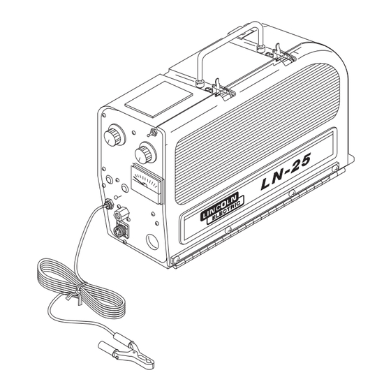
LN-25 PORTABLE CV/CC
SEMIAUTOMATIC WIRE FEEDER
Safety Depends on You
Lincoln arc welding and cutting
equipment is designed and built with
safety in mind. However, your overall
safety can be increased by proper
installation ... and thoughtful opera-
tion on your part. DO NOT
INSTALL, OPERATE OR REPAIR
THIS EQUIPMENT WITHOUT
READING THIS MANUAL AND
THE SAFETY PRECAUTIONS
CONTAINED THROUGHOUT. And,
most importantly, think before you
act and be careful.
• Sales and Service through Subsidiaries and Distributors Worldwide •
Cleveland, Ohio 44117-1199 U.S.A. TEL: 216.481.8100 FAX: 216.486.1751 WEB SITE: www.lincolnelectric.com
For use with machines having Code Number
RETURN TO MAIN MENU
OPERATING MANUAL
• World's Leader in Welding and Cutting Products •
10556
11144
10557
11145
10558
11282
11283
Copyright © 2006 Lincoln Global Inc.
IM620-B
November, 2006
Advertisement
Table of Contents

Related Manuals for Lincoln Electric LN-25 PORTABLE CV/CC IM620-B


Summary of Contents for Lincoln Electric LN-25 PORTABLE CV/CC IM620-B
- Page 1 LN-25 PORTABLE CV/CC SEMIAUTOMATIC WIRE FEEDER For use with machines having Code Number Safety Depends on You Lincoln arc welding and cutting equipment is designed and built with safety in mind. However, your overall safety can be increased by proper installation ...
-
Page 2: California Proposition 65 Warnings
Welding & Cutting - ANSI Standard Z49.1” from the American Welding Society, P.O. Box 351040, Miami, Florida 33135 or CSA Standard W117.2-1974. A Free copy of “Arc Welding Safety” booklet E205 is available from the Lincoln Electric Company, 22801 St. Clair Avenue, Cleveland, Ohio 44117-1199. -
Page 3: Electric Shock Can Kill
ELECTRIC SHOCK can kill. 3.a. The electrode and work (or ground) circuits are electrically “hot” when the welder is on. Do not touch these “hot” parts with your bare skin or wet clothing. Wear dry, hole-freegloves to insulate hands. 3.b. Insulate yourself from work and ground using dry insulation. - Page 4 WELDING SPARKS can cause fire or explosion. 6.a. Remove fire hazards from the welding area. If this is not possible, cover them to prevent the welding sparks from starting a fire. Remember that welding sparks and hot materials from welding can easily go through small cracks and openings to adjacent areas.
- Page 5 PRÉCAUTIONS DE SÛRETÉ Pour votre propre protection lire et observer toutes les instructions et les précautions de sûreté specifiques qui parraissent dans ce manuel aussi bien que les précautions de sûreté générales suivantes: Sûreté Pour Soudage A L’Arc 1. Protegez-vous contre la secousse électrique: a.
- Page 6 The code number is especially important when identifying the correct replacement parts. - Register your machine with Lincoln Electric either via fax or over the Internet. • For faxing: Complete the form on the back of the warranty statement included in the literature packet accompanying this machine and fax the form per the instructions printed on it.
-
Page 7: Table Of Contents
SAFETY ...i-iv INSTALLATION ...SECTION A Technical Specifications ...A-1 Safety Precautions ...A-2 Power Source Connections...A-2 Gun Cable Connection to Feeder ...A-3 Weld Cable Connection ...A-4 Electrode Cable Connection...A-4 Work Cable Connection ...A-4 Wire Feed Drive Roll and Guide Tube Kits ...A-4 OPERATION...SECTION B Safety Precautions ...B-1 General Description...B-1... -
Page 8: Installation
TECHNICAL SPECIFICATIONS – LN-25 Constant Voltage (CV) Constant Current (CC) Rated current without contactor Rated current with contactor RECOMMENDED ELECTRODE WIRE SIZES ⁄ ” .023” to ⁄ ” .045” to ⁄ ” 035” to HEIGHT (Handle Down) 14 Inches (354 mm) OPERATION: - 40 STORAGE:... -
Page 9: Safety Precautions
SAFETY PRECAUTIONS WARNING Unless an optional output control or contactor is used with the LN-25, the electrode circuit (including welding wire, wire drive and welding gun) is electrically hot when the welding power source is on. The gun trigger controls wire feed only. Disconnect or shut off welding power source before making connections or installations to the LN-25. -
Page 10: Gun Cable Connection To Feeder
Set ELECTRODE POLARITY switch to constant voltage polarity required by electrode. d. Set toggle switch to “Constant Voltage” and set the Constant Voltage Control on welder and the portable field control on #5 for initial start. SA-200, —250 OR SAE-300, —400 (WITH CV ADAPTER) a. -
Page 11: Weld Cable Connection
Install the barbed fitting and union nut to the female inert gas fitting on the front panel of the LN-25 case. Connect the ⁄ ” I.D. gas hose from the gun cable to the barbed fitting. When the gun is to be removed, this fitting can be easily detached by loosening the union nut. -
Page 12: Operation
SAFETY PRECAUTIONS READ AND UNDERSTAND ENTIRE SECTION BEFORE OPERATING MACHINE WARNING ELECTRIC SHOCK can kill. • Do not touch electrically live part or electrode with skin or wet clothing. • Insulate yourself from work and ground. • Always wear dry insulating gloves. -
Page 13: Instruments And Controls
LN-25 INSTRUMENTS AND CONTROLS Refer to Figure B.1 for control locations. REMOTE WIRE SPEED ARC VOLTAGE DIAL RANGE CONTROL SWITCH (OPTIONAL) GAS POST/ PRE FLOW TIMERS (OPTIONAL) ELECTRODE POLARITY SWITCH FITTING (OPTIONAL) TRIGGER AMPHENOL CONNECTOR FIGURE B.1 CONTROL LOCATIONS VOLTMETER (Factory installed on model Codes above 9218) The 40V DC analog voltmeter is mounted to the front control panel of the LN-25 and is connected to read... - Page 14 The volts marks around the HI range calibrated dial indicate the minimum arc volts required to obtain the indicated HI range wire feed speeds. For example; if wire speed is set to 400 in/min., a welding procedure arc voltage of at least 17V would be required to obtain the 400 in/min.
-
Page 15: Sequence Of Operation
SEQUENCE OF OPERATION LOADING ELECTRODE WARNING ELECTRIC SHOCK can kill. • Unless an optional output control or internal contactor is used with the LN-25, the electrode circuit is electrically “Hot” when the power source is on. • Turn off the power source while mounting electrode coils. -
Page 16: Loading Wire Drive
1. Press end of gun against a solid object that is electrically isolated from the welder output. Press the gun trigger for several seconds. 2. If the wire “bird nests,” jams or breaks at the drive roll, the idle roll pressure is too great. -
Page 17: Presetting Wire Feed Speed
3. If the only result is drive roll slippage, shut off the power source, then loosen the gun cable clamping screw in the gearbox conductor block and pull the gun cable forward about six inches. There should be a slight waviness in the exposed wire. -
Page 18: Making A Weld
LN-25 wire feeder is and must be the sole responsibility of the builder/user. Many variables beyond the control of The Lincoln Electric Company affect the results obtained in using the LN-25 wire feeder. These variables include, but are not limited to,... -
Page 19: Procedure At End Of Coil
• Keep cylinder upright and chained to support. • Keep cylinder away from areas where it may be dam- aged. • Never lift welder with cylin- der attached • Never allow welding elec- trode to touch cylinder. • Keep cylinder away from welding or other live electri- cal circuits. -
Page 20: Automatic Protection Shutdown
CAUTION Do not use LN-25 models below Code 9200 with any TIG or Square Wave welding power sources. Do not use LN-25 models equipped with internal contactors with non-Lincoln TIG or Square Wave welding power sources. Damage to the LN-25 circuit can occur as a result of the high output inductance typically associated with these power sources. -
Page 21: Accessories
IMPORTANT SAFETY NOTE: This wire feeder provides “COLD” electrode when gun trigger is released if equipped with K431-1, K432 or K433 remote output control system, or K443-2 internal contactor kit. This feature and the use of a DC Constant Voltage welder provide an added margin of safety when welding must be performed under electrically hazardous conditions such as: •... -
Page 22: Options And Accessories
OPTIONAL ACCESSORIES • Keep cylinder away from areas where it may be damaged. • Never lift welder with cylinder attached. • Never allow welding electrode to touch cylinder. • Keep cylinder away from welding or other live elec- trical circuits. -
Page 23: K460-1 Pulse Power Adapter Kit
K460-1 PULSE POWER ADAPTER KIT (For use with K461 Pulse Power Control Cable.)(No Longer Available) This kit enables the LN-25 to pulse weld with a Pulse Power 500 power source above Code 9300 (or lower Codes updated with Kit). The kit includes a Remote PC board with output volt- age control, and control cable receptacle which mount and connect inside the LN-25 control box per the Installation Instructions (L9636) included with the kit. -
Page 24: K433 Power Source Remote Box
The Kit includes a Remote PC board and control cable receptacle which mount and connect inside the LN-25 control box per the Installation Instructions (M17584) included with the kit. NOTE: If the K431-1 Remote Output Control Kit is installed but the LN-25 is to be used without the K432 Remote Control Cable Assembly, then the Re- mote Board harness plug must be removed from the 16-pin receptacle on the Control Board and the... -
Page 25: K444, K444-1 Or K444-2 Remote Voltage Control Kit
The cable assembly end with the socket pin connector connects to the LN-25 per the Instructions (M17253) included with the K624-1 Kit. CABLE 60% DUTY TYPE RATING K625 500 Amps K626 350 Amps K627 400 Amps The cable assembly end with the male pin connector connects to the power source per the Instructions (M17253) included with the K624-1 kit. - Page 26 The following Figures C.1 and C.2 should serve as a guide to determine if a particular gun or switch can be connected to the LN-25. GUN CABLE CONNECTOR REQUIREMENTS TO PERMIT PROPER CONNECTION TO LINCOLN LN-25 WIRE FEEDER. NOTE: Connector part with .749/.747 diameter should be made from brass if it is to be part of the welding current carrying circuit.
-
Page 27: Maintenance
SAFETY PRECAUTIONS WARNING ELECTRIC SHOCK can kill. • Do not operate with covers removed. • Turn off power source before installing or servicing. • Do not touch electrically hot parts. • Turn the input power to the welding power source off at the fuse box before working in the terminal strip. -
Page 28: Calibration Of The Ln-25 Wire Speed Dial
1. Be sure all power to the LN-25 is shut off at the power source. 2. Check that the module mounting plate is screwed securely to the side of the gearbox. 3. Gently screw the module into the mounting plate until it just touches and stops against the rotating part inside the gearbox. -
Page 29: Troubleshooting
HOW TO USE TROUBLESHOOTING GUIDE Service and Repair should only be performed by Lincoln Electric Factory Trained Personnel. Unauthorized repairs performed on this equipment may result in danger to the technician and machine operator and will invalidate your factory warranty. For your safety and to avoid Electrical Shock, please observe all safety notes and precautions detailed throughout this manual. -
Page 30: Feeding Problems
PROBLEMS (SYMPTOMS) No wire feed when gun trigger is pulled Wire feeds for a short time but stops feeding. When gun trigger is released and retriggered wire feeding starts but stops again. Wire feeds OK, but stubs or stops while welding. If for any reason you do not understand the test procedures or are unable to perform the tests/repairs safely, con- tact your local authorized field service facility for technical troubleshooting assistance before you proceed. - Page 31 PROBLEMS (SYMPTOMS) Rough wire feeding or wire not feeding but drive rolls turning. If for any reason you do not understand the test procedures or are unable to perform the tests/repairs safely, con- tact your local authorized field service facility for technical troubleshooting assistance before you proceed. TROUBLESHOOTING POSSIBLE CAUSE...
-
Page 32: Output Problems
PROBLEMS (SYMPTOMS) Solenoid does not close when trigger is pulled or purge button is pressed. Wire feeds properly. Variable or “hunting” arc. Weld porosity, narrow and ropey bead, or electrode stubbing into plate when welding. Motor feeds but there is no wire feed speed control. -
Page 33: Wiring Diagram
WIRING DIAGRAM LN-25... - Page 34 WIRING DIAGRAM LN-25...
-
Page 35: Ln-25 Physical Dimensions
DIMENSIONS LN-25 PHYSICAL DIMENSIONS 16.60 14.00 21.00 7.40 LN-25... - Page 36 NOTES LN-25...
- Page 37 NOTES LN-25...
- Page 38 ● WARNING ● Spanish ● AVISO DE PRECAUCION ● French ● ATTENTION ● ● German WARNUNG ● Portuguese ● ATENÇÃO ● Japanese Chinese Korean Arabic READ AND UNDERSTAND THE MANUFACTURER’S INSTRUCTION FOR THIS EQUIPMENT AND THE CONSUMABLES TO BE USED AND FOLLOW YOUR EMPLOYER’S SAFETY PRACTICES. SE RECOMIENDA LEER Y ENTENDER LAS INSTRUCCIONES DEL FABRICANTE PARA EL USO DE ESTE EQUIPO Y LOS CONSUMIBLES QUE VA A UTILIZAR, SIGA LAS MEDIDAS DE SEGURIDAD DE SU SUPERVISOR.
- Page 39 ● ● Keep your head out of fumes. Turn power off before servicing. ● Use ventilation or exhaust to remove fumes from breathing zone. ● Los humos fuera de la zona de res- ● Desconectar el cable de ali- piración. mentación de poder de la máquina ●...
- Page 40 • World's Leader in Welding and Cutting Products • • Sales and Service through Subsidiaries and Distributors Worldwide • Cleveland, Ohio 44117-1199 U.S.A. TEL: 216.481.8100 FAX: 216.486.1751 WEB SITE: www.lincolnelectric.com...
Need help?
Do you have a question about the LN-25 PORTABLE CV/CC IM620-B and is the answer not in the manual?
Questions and answers