Table of Contents
Advertisement
Quick Links
Advertisement
Table of Contents

Related Manuals for A-M Systems 1900


Summary of Contents for A-M Systems 1900
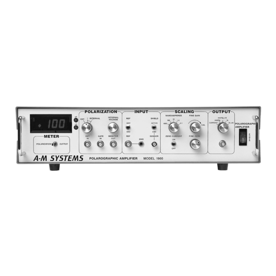
- Page 2 INSTRUCTION MANUAL POLAROGRAPHIC AMPLIFIER MODEL 1900 Serial #__________ Date____________ A-M Systems PO Box 850 Carlsborg, WA 98324 U.S.A. ♦ 360-683-8300 800-426-1306 FAX: 360-683-3525 http://www.a-msystems.com Version 9.0 March 2020...
-
Page 3: Table Of Contents
..........................17 Each Polarographic Amplifier is delivered complete with: Rack Mount Hardware NOTE This instrument is not intended for clinical measurements using human subjects. A-M Systems does not assume responsibility for injury or damage due to the misuse of this instrument. -
Page 4: General Description
The Model 1900 converts the input current to an output voltage, scaled and offset by user operated controls. The voltage is output for subsequent analysis by the researcher. -
Page 5: Controls And Connectors
Controls and Connectors The Model 1900 has been designed to ease polarographic measurements, while accommodating the imperfections of real electrodes. This section gives a brief description of the controls and connectors. INPUT section is directly associated with the electrodes. INPUT The sensing electrode is connected to the input. - Page 6 5-decade METER sensitivity range without loss of resolution. 131 Business Park Loop, P.O. Box 850 Carlsborg, WA 98324 A-M Systems Telephone: 800-426-1306 * 360-683-8300 * FAX: 360-683-3525 E-mail: sales@a-msystems.com * Website: http://www.a-msystems.com...
-
Page 7: Operating Instructions
Operating Instructions The Model 1900 has been designed to be simple and intuitive to operate, while allowing a high degree of flexibility and performance. A brief description of pertinent polarographic electrode characteristics is included in this section along with operating instructions for the instrument and solutions to common problems which are encountered in its use, in order to assist with the effective use of this instrument. - Page 8 2 electrode configuration. The amount of current flowing through most polarographic electrodes is low enough that this should not be a problem for nearly all researchers. 131 Business Park Loop, P.O. Box 850 Carlsborg, WA 98324 A-M Systems Telephone: 800-426-1306 * 360-683-8300 * FAX: 360-683-3525 E-mail: sales@a-msystems.com * Website:...
-
Page 9: Instrument Set-Up And Calibration
Instrument Set-Up and Calibration Note: In most cases, the settings of the Model 1900 will not have to be changed from experiment to experiment, except for calibrating the electrodes. Connecting the Electrodes to the Input The characteristics of polarographic electrodes make it necessary to exercise extreme care in connecting the Model 1900 with the electrode set. - Page 10 While a specific application may be different, the calibration procedure will likely be analogous. In addition to the electrode set, cables, and the Model 1900, a method must exist to control the concentration of the substance being measured. The test solution should mimic the features of the tissue to be tested later.
- Page 11 Connect the electrode set (2 electrode or 3 electrode) to the Model 1900 as described above. The test solution should have as low a concentration of the substance as possible.
-
Page 12: Problem Solving
“stir artifact” effect. Membranes over the sensing surface greatly reduce this effect. The “Clark” oxygen electrode is a classic implementation of this approach. To test the basic functionality of the Model 1900, replace the electrode with a 10 MV resistor. Set switches to the position. - Page 13 CURRENT If the Model 1900 appears to be malfunctioning, contact A-M Systems, Inc., or the dealer from which the instrument was purchased. Contact information for A-M Systems, Inc. is listed on the cover page of this manual. Further information may also be found in the section “Warranty and Service”...
-
Page 14: Theory Of Operation
Theory Of Operation The operation of the Model 1900 is summarized in the block diagram below (Figure 4). The most critical portion of the instrument is the Current to Voltage transducer (U100, U101, U102, U500A). This section accepts the polarization voltage, adds the reference voltage, and applies it to the input. - Page 15 The decimal points are suppressed when the meter is set to read the polarization voltage; the readout is then in mV. 131 Business Park Loop, P.O. Box 850 Carlsborg, WA 98324 A-M Systems Telephone: 800-426-1306 * 360-683-8300 * FAX: 360-683-3525 E-mail: sales@a-msystems.com * Website:...
-
Page 16: Specifications
Voltage compliance range (offset between reference, gnd) ± 12 V Maximum continuous applied voltage (without breakdown) 131 Business Park Loop, P.O. Box 850 Carlsborg, WA 98324 A-M Systems Telephone: 800-426-1306 * 360-683-8300 * FAX: 360-683-3525 E-mail: sales@a-msystems.com * Website: http://www.a-msystems.com... - Page 17 Gate OFF Monitor Output Ω Output impedance ± 2% Accuracy Within ± (2% + 15 mV) 131 Business Park Loop, P.O. Box 850 Carlsborg, WA 98324 A-M Systems Telephone: 800-426-1306 * 360-683-8300 * FAX: 360-683-3525 E-mail: sales@a-msystems.com * Website: http://www.a-msystems.com...
- Page 18 . This applies at 25°C ambient temperature. Somewhat greater offsets may occur at higher temperatures. See the INPUT section for more details. 131 Business Park Loop, P.O. Box 850 Carlsborg, WA 98324 A-M Systems Telephone: 800-426-1306 * 360-683-8300 * FAX: 360-683-3525 E-mail: sales@a-msystems.com * Website:...
- Page 19 ± 5 mA (minimum, short circuit) Note: Higher output currents are available, but system accuracy is not guaranteed. 131 Business Park Loop, P.O. Box 850 Carlsborg, WA 98324 A-M Systems Telephone: 800-426-1306 * 360-683-8300 * FAX: 360-683-3525 E-mail: sales@a-msystems.com * Website:...
-
Page 20: Warranty And Service
What are the obligations of A-M Systems under this warranty? During the warranty period, A-M Systems agrees to repair or replace, at its sole option, without charge to the Purchaser, any defective component part of the hardware. To obtain warranty service, the Purchaser must return the hardware to A-M Systems or an authorized A-M Systems distributor in an adequate shipping container. - Page 21 What are the limits of liability for A-M Systems under this warranty? A-M Systems shall not be liable for loss of data, lost profits or savings, or any special, incidental, consequential, indirect or other similar damages, whether arising from breach of contract, negligence, or other legal action, even if the company or its agent has been advised of the possibility of such damages, or for any claim brought against you by another party.
- Page 22 A-M Systems Model 1900 Manual DRW-5026700 rev 9 Revision History Date Description 6/30/06 Initial Document Control release 4/28/10 DCR 201200 Warranty and company info 1/17/17 DCR 202465. Remove Calibration information. 1/18/19 DCR 202615. Review conent. Add rev control to content.
Need help?
Do you have a question about the 1900 and is the answer not in the manual?
Questions and answers