Table of Contents
Advertisement
Quick Links
Advertisement
Table of Contents

Related Manuals for A-M Systems 3000


Summary of Contents for A-M Systems 3000
- Page 2 INSTRUCTION MANUAL AC/DC DIFFERENTIAL AMPLIFIER MODEL 3000 Serial #__________ Date____________ A-M Systems PO Box 850 Carlsborg, WA 98324 U.S.A. ♦ 360-683-8300 800-426-1306 FAX: 360-683-3525 http://www.a-msystems.com Version 7.0 March 2020...
-
Page 3: Table Of Contents
Contents General Description ..........................1 Instrument Features ........................... 1 Controls and Connectors ........................1 Configuring the Model 3000 for use with a head stage ..............5 Operating Instructions ........................6 Typical Set-Up Procedure ........................6 Theory of Operation ........................... 9 Specifications ............................. -
Page 4: General Description
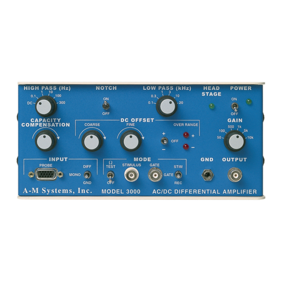
(EMG), EEG, EKG, and ERG recordings. The instrument is not intended for clinical measurements using humans. The Model 3000 contains a high-gain, low-noise differential amplifier stage followed by low frequency, high-frequency, and notch filters. Three operating modes are available to accommodate recording, stimulating, and verification of electrode impedance. - Page 5 When the unit is in the (STIM) mode the output will be a measure of the current passing through the electrode in six ranges (5V/mA, 10V/mA, 50mV/µA, 0.1V/µA, 0.2V/ µA, or 1V/µA). This toggle switch controls the operating mode for the Model 3000. STIM-GATE-REC: The switches allows the user to select Record Mode (...
- Page 6 This switch allows the Notch Filter (-50dB at 60Hz) to be included in the signal NOTCH: processing path ( ) or bypassed ( ). Warning: Although the Notch Filter provided 131 Business Park Loop, P.O. Box 850 Carlsborg, WA 98324 A-M Systems Telephone: 800-426-1306 * 360-683-8300 * FAX: 360-683-3525 E-mail: sales@a-msystems.com * Website: http://www.a-msystems.com...
- Page 7 This LED indicates whether the unit is configured for use with ( HEAD STAGE: HEAD lit) or without ( off) a head stage (See configuring the Model 3000 STAGE HEAD STAGE for use with a head stage pg. 5). Power Supply...
-
Page 8: Configuring The Model 3000 For Use With A Head Stage
3000 you will need to complete the following procedure. To set the model 3000 for use with a head stage, all jumpers must be set to the H position (see figure 2 below). Once the jumpers are in the H position the unit can only be used with a head stage. -
Page 9: Operating Instructions
Operating Instructions Typical Set-Up Procedure The Model 3000 comes with an input cable that connects to the DB15 input. One end of this cable is left open to allow for maximum flexibility in connecting to extracellular electrodes. The Model 3000 will function properly in this configuration if the head stage ) LED is off. - Page 10 Ω TEST 3. Turn on power to the Model 3000 and allow it to warm up for 5 minutes. 4. Non Headstage option: connect measuring electrode to the black wire and a reference electrode to the white wire of the probe cable.
- Page 11 The mounting rod can be screwed into the cable end of the head stage for in- line mounting. 131 Business Park Loop, P.O. Box 850 Carlsborg, WA 98324 A-M Systems Telephone: 800-426-1306 * 360-683-8300 * FAX: 360-683-3525 E-mail: sales@a-msystems.com * Website:...
-
Page 12: Theory Of Operation
Theory of Operation Overview The Model 3000 is a high gain differential AC/DC amplifier. The first stage in the amplifier (with either the head stage option or non head stage version) consists of a high input impedance differentially coupled x50 amplifier. The signal from this amplifier is coupled through positive feedback with a capacitor to form capacity compensation. - Page 13 2nA p-p at 100 Hz. The calibrated current source is connected to the electrode leads. 131 Business Park Loop, P.O. Box 850 Carlsborg, WA 98324 A-M Systems Telephone: 800-426-1306 * 360-683-8300 * FAX: 360-683-3525 E-mail: sales@a-msystems.com * Website:...
-
Page 14: Specifications
Common mode rejection 90dB Notch Filter Better than -50dB at 60Hz; Better than -45dB at 50Hz 131 Business Park Loop, P.O. Box 850 Carlsborg, WA 98324 A-M Systems Telephone: 800-426-1306 * 360-683-8300 * FAX: 360-683-3525 E-mail: sales@a-msystems.com * Website: http://www.a-msystems.com... - Page 15 8.5 inches (21.6 cm) Height 4 inches (10.2 cm) Depth 3.5 inches (8.9 cm) Weight 5 pounds 131 Business Park Loop, P.O. Box 850 Carlsborg, WA 98324 A-M Systems Telephone: 800-426-1306 * 360-683-8300 * FAX: 360-683-3525 E-mail: sales@a-msystems.com * Website: http://www.a-msystems.com...
-
Page 16: Warranty And Service
What are the obligations of A-M Systems under this warranty? During the warranty period, A-M Systems agrees to repair or replace, at its sole option, without charge to the Purchaser, any defective component part of the hardware. To obtain warranty service, the Purchaser must return the hardware to A-M Systems or an authorized A-M Systems distributor in an adequate shipping container. - Page 17 What are the limits of liability for A-M Systems under this warranty? A-M Systems shall not be liable for loss of data, lost profits or savings, or any special, incidental, consequential, indirect or other similar damages, whether arising from breach of contract, negligence, or other legal action, even if the company or its agent has been advised of the possibility of such damages, or for any claim brought against you by another party.
- Page 18 A-M Systems 3000 Manual DRW-5027901 rev 7 Approved: Revision History Date Description 6/30/06 Initial Document Control release 4/28/10 DCR201200 Warranty and Company info 11/20/15 DCR 202472, 202512. Correct for x10Hs 2/27/17 DCR 202739. Correct Rev Numbering 1/18/19 DCR 202615. Review content, add content rev control 3/19/20 DCR 203316.
Need help?
Do you have a question about the 3000 and is the answer not in the manual?
Questions and answers