Table of Contents
Advertisement
Quick Links
Advertisement
Table of Contents

Related Manuals for A-M Systems 3600


Summary of Contents for A-M Systems 3600
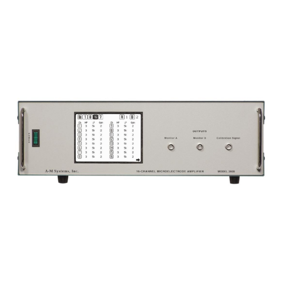
- Page 2 INSTRUCTION MANUAL 16-CHANNEL EXTRACELLULAR AMPLIFIER WITH HEADSTAGE MODEL 3600 Each 16-Channel Extracellular Amplifier is delivered complete with: User Selected 16-Channel Headstage 10’ USB Cable Rack Mount Hardware Instruction Manual Version 6.0 January 2019 A-M Systems PO Box 850 Carlsborg, WA 98324 U.S.A.
- Page 3 Replace fuse only with specified and should not be construed as a type. The Warning symbol calls attention commitment by A-M Systems, to a procedure or practice, which, if Changes may have been made to Supply Voltage not correctly performed could...
-
Page 4: Table Of Contents
Figure 40. Toolbar with TTL Icon ....42 9. WARRANTY ........46 Figure 41. Diagram of External TTL Connector Pin Layout ..........43 A-M Systems, Inc. PO BOX 850, Carlsborg, WA 98324 USA Telephone: 800-426-1306 * 360-683-8300 * FAX: 360-683-3525 E-mail: sales@a-msystems.com * Website: http://www.a-msystems.com... -
Page 5: General Description
1. General Description The Model 3600 contains 16 low noise, high gain full-featured extracellular amplifiers, or channels, designed for amplifying microvolt-level input signals. It is paired with several headstage options, including a Record- Only Miniature headstage, and a Stimulating and Recording Headstage. All parameters can be controlled via the unit’s touch screen LCD display on the front panel or via a USB link to a personal computer running a... -
Page 6: Front And Rear Panels
Chapters 3 and 4 describe the individual screens available on the touch-screen LCD interface. When you receive your Model 3600, confirm that everything in the packing list is included. Make sure there are no obvious signs of internal damage, such as rattling. Pick up the amplifier and tilt in gently from side to side, and listen for anything that might be loose. -
Page 7: Rear Panel
Record only headstage is used. Figure 7. Probe Stimulation Control Stim Stim Plus M inus A-M Systems, Inc. PO BOX 850, Carlsborg, WA 98324 USA Telephone: 800-426-1306 * 360-683-8300 * FAX: 360-683-3525 E-mail: sales@a-msystems.com * Website: http://www.a-msystems.com... - Page 8 Stimulation Inputs different stimulation signals / sources can be utilized. The Model 3600 can be set to pass the signal present at STIM1 or STIM2 to desired channels. The outer conductor connects to Ext Ref Channel while the inner conductor connects to the selected channels input leads.
- Page 9 Figure 12. USB Connector Windows operating system compatible control program to ® control the Model 3600 by attaching it to an available USB port on the computer using the USB cable supplied with the instrument. Ground Connector Figure 13. Ground Connector This banana jack (Figure 13) is the amplifier’s chassis (signal)
- Page 10 The Model 3600 should be delivered with the appropriate mains power voltage set, at either 100-120 volts or 220-240 volts. A red slide switch located on the back panel just above the power input determines this setting.
-
Page 11: Instrument Operation
The touch-screen LCD should illuminate and the A-M Systems logo should be displayed briefly as the on-board software loads. After the initial software loads, the Calibrate Screen Process will begin. By touching the indicated targets, the software responsible for tracking user input will determine the user’s local pressure... - Page 12 ON implements the filter. OFF removes the filter. The NOTCH filter can be tuned for the AC line frequency in the country where the Model 3600 is being used by accessing the NOTCH FILTER PAGE via the MAIN MENU (See Chapter 4).
-
Page 13: Channels
At this point, the unit is defined and functional on all channels. Further details on all instrument functions are described in the next chapter. A-M Systems, Inc. PO BOX 850, Carlsborg, WA 98324 USA Telephone: 800-426-1306 * 360-683-8300 * FAX: 360-683-3525... -
Page 14: Touch Screen Menus
Displays Output Monitor A setting; Calls Monitor setting screen. Monitor B Displays Output Monitor B setting; Calls Monitor setting screen. A-M Systems, Inc. PO BOX 850, Carlsborg, WA 98324 USA Telephone: 800-426-1306 * 360-683-8300 * FAX: 360-683-3525 E-mail: sales@a-msystems.com * Website: http://www.a-msystems.com... -
Page 15: Main Menu Screen
Additional details on each of these screen options follow. Figure 18. Main Menu Screen A-M Systems, Inc. PO BOX 850, Carlsborg, WA 98324 USA Telephone: 800-426-1306 * 360-683-8300 * FAX: 360-683-3525 E-mail: sales@a-msystems.com * Website: http://www.a-msystems.com... -
Page 16: Load Screen
Load Screen LOAD screen displays a list of five memory locations that are stored within the Model 3600 and are saved even after AC power to the unit is shut off. These memory locations store the critical parameters of all 16-channels in a single file. A memory location is selected by highlighting the parameter set name (or program) name. -
Page 17: Save Screen
SHIFT will toggle the screen from capital letters to lower case letters. Figure 20. Save Screen A-M Systems, Inc. PO BOX 850, Carlsborg, WA 98324 USA Telephone: 800-426-1306 * 360-683-8300 * FAX: 360-683-3525 E-mail: sales@a-msystems.com * Website: http://www.a-msystems.com... -
Page 18: Set Startup Program
CANCEL terminates the process and makes no change to the current startup program selection. Figure 21. Set Startup Screen A-M Systems, Inc. PO BOX 850, Carlsborg, WA 98324 USA Telephone: 800-426-1306 * 360-683-8300 * FAX: 360-683-3525 E-mail: sales@a-msystems.com * Website: http://www.a-msystems.com... -
Page 19: Instrument Name Screen
MAIN MENU. CANCEL does not store the new name, and the unit returns to the MAIN MENU. Figure 22. Instrument Name Screen A-M Systems, Inc. PO BOX 850, Carlsborg, WA 98324 USA Telephone: 800-426-1306 * 360-683-8300 * FAX: 360-683-3525 E-mail: sales@a-msystems.com * Website: http://www.a-msystems.com... -
Page 20: Input Screen
STIM mode. If you plan on stimulating, it is preferred to either reference your recording channels to ground, or to another channel, but not the x10 Ref line. A-M Systems, Inc. PO BOX 850, Carlsborg, WA 98324 USA Telephone: 800-426-1306 * 360-683-8300 * FAX: 360-683-3525 E-mail: sales@a-msystems.com * Website: http://www.a-msystems.com... - Page 21 DONE returns the unit to the last displayed channel screen (CHANNEL EDIT, 8-CHANNEL VIEW, or 16-CHANNEL VIEW). Figure 24. Notch Filter Screen A-M Systems, Inc. PO BOX 850, Carlsborg, WA 98324 USA Telephone: 800-426-1306 * 360-683-8300 * FAX: 360-683-3525 E-mail: sales@a-msystems.com * Website: http://www.a-msystems.com...
-
Page 22: Stimulation Inputs
Ref line. DONE returns the unit to the last displayed channel screen (CHANNEL EDIT, 8-CHANNEL VIEW, or 16-CHANNEL VIEW). A-M Systems, Inc. PO BOX 850, Carlsborg, WA 98324 USA Telephone: 800-426-1306 * 360-683-8300 * FAX: 360-683-3525... -
Page 23: Calibration Signal
The REVERSE LCD button will reverse the color of the screen from dark letters on a light background, to light letters on a back background, and back again. Figure 26. Contrast Screen A-M Systems, Inc. PO BOX 850, Carlsborg, WA 98324 USA Telephone: 800-426-1306 * 360-683-8300 * FAX: 360-683-3525 E-mail: sales@a-msystems.com * Website: http://www.a-msystems.com... -
Page 24: Calibrate Lcd Screen
STARTUP PAGE screen. Figure 27. Calibrate LCD Screens A-M Systems, Inc. PO BOX 850, Carlsborg, WA 98324 USA Telephone: 800-426-1306 * 360-683-8300 * FAX: 360-683-3525 E-mail: sales@a-msystems.com * Website: http://www.a-msystems.com... -
Page 25: Startup Page Screen
Start-up Page Version Screen The VERSION screen displays the latest version numbers of the software and hardware the Model 3600 currently uses. This diagnostic tool should be used before contacting A-M Systems for service. Figure 29. Version Screen A-M Systems, Inc. -
Page 26: Channel Edit Screen
EDIT SCREEN. ALL selects all the channels; NONE clears the channels selected. Pressing COPY will then transfer the channel parameters to the selected channels. A-M Systems, Inc. PO BOX 850, Carlsborg, WA 98324 USA Telephone: 800-426-1306 * 360-683-8300 * FAX: 360-683-3525... -
Page 27: 8-Channel View Screen
CHANNEL EDIT SCREEN, those same channels will now be selected in the in the double rows of that screen’s MULTICHANNEL SELECT LIST. A-M Systems, Inc. PO BOX 850, Carlsborg, WA 98324 USA Telephone: 800-426-1306 * 360-683-8300 * FAX: 360-683-3525... -
Page 28: 16-Channel View Screen
(Notch, (-) In, and Mode). Figure 34. Figure 33. 16-Channel View Screen Two 16-Channel View Screen One A-M Systems, Inc. PO BOX 850, Carlsborg, WA 98324 USA Telephone: 800-426-1306 * 360-683-8300 * FAX: 360-683-3525 E-mail: sales@a-msystems.com * Website: http://www.a-msystems.com... -
Page 29: Signal Screen
Output Monitors and Calibration Signal Screen For user convenience, the Model 3600 has two channel output monitors (BNC connectors A and B) available on the front panel. Pressing “A” or “B” at the top right-hand corner of any screen will display the CHANNEL MONITOR and CALIBRATION SIGNAL Screen. - Page 30 Figure 35. Monitor and Calibration Signal Screen A-M Systems, Inc. PO BOX 850, Carlsborg, WA 98324 USA Telephone: 800-426-1306 * 360-683-8300 * FAX: 360-683-3525 E-mail: sales@a-msystems.com * Website: http://www.a-msystems.com...
-
Page 31: Headstage Options
5. Headstage Options There are two headstage options for use with the Model 3600 16-Channel Extracellular Amplifier: A Stimulating and Recording Headstage (below left), and a smaller Recording-Only Headstage (below right). Each headstage uses the same input connector. Unused inputs should be grounded for optimal amplifier performance. - Page 32 11 12 13 14 15 16 17 18 Note: Position 1 must be connected to either ground or a reference electrode. A-M Systems, Inc. PO BOX 850, Carlsborg, WA 98324 USA Telephone: 800-426-1306 * 360-683-8300 * FAX: 360-683-3525 E-mail: sales@a-msystems.com * Website: http://www.a-msystems.com...
-
Page 33: Pc Control Software
6. PC Control Software The Model 3600 can be controlled by Windows compatible software that is available for download at www.a-msystems.com. The downloadable control software runs on Windows 10, 7, and, ® Windows XP. The section that follows covers installation procedures for Windows 10. If you ®... - Page 34 Extract the files to a new folder: The Model 3600 control software requires the Microsoft® .NET Framework version 1.1 or later to function. Once extracted, double click to run the “dotnetfx.exe” file. A-M Systems, Inc. PO BOX 850, Carlsborg, WA 98324 USA Telephone: 800-426-1306 * 360-683-8300 * FAX: 360-683-3525 E-mail: sales@a-msystems.com * Website: http://www.a-msystems.com...
- Page 35 An additional dialog box to begin .NET installation. Select “I agree” to proceed. After .Net is installed, a dialog box will appear. Click “OK” to close. A-M Systems, Inc. PO BOX 850, Carlsborg, WA 98324 USA Telephone: 800-426-1306 * 360-683-8300 * FAX: 360-683-3525...
- Page 36 Return to the installation software folder and double click on “Setup.exe” to install the Model 3600 Control Software. The Model 3600 control software installation wizard will ask for permission to install: A-M Systems, Inc. PO BOX 850, Carlsborg, WA 98324 USA Telephone: 800-426-1306 * 360-683-8300 * FAX: 360-683-3525 E-mail: sales@a-msystems.com * Website: http://www.a-msystems.com...
- Page 37 A dialog box suggesting the file location will open. A question asks for who should be able to use the pc control software. Select “Everyone” and click “Next” A-M Systems, Inc. PO BOX 850, Carlsborg, WA 98324 USA Telephone: 800-426-1306 * 360-683-8300 * FAX: 360-683-3525...
- Page 38 Confirm that you want to install the software by clicking “Next.” Once installation is complete, a final dialog box will be displayed: Press “Close” to exit. A-M Systems, Inc. PO BOX 850, Carlsborg, WA 98324 USA Telephone: 800-426-1306 * 360-683-8300 * FAX: 360-683-3525...
-
Page 39: Using The Controls
Using the Control Software After the program has been installed, you can run it from the Start Menu by selecting Programs -> A-M Systems -> Amplifier Control Panel Figure 38. PC Software If your program loaded successfully, after a brief display of our company logo, the program window shown in Figure 36 should appear. - Page 40 If the Model 3600 is turned on and attached to the computer when the control software is executed, then the instrument name and serial number should appear in the list located in the upper left corner of the main window under the heading INSTRUMENTS/FILES. If it is not listed, or if it is connected to the computer after the control software is started, select Refresh from the Instruments menu (or press F5) to refresh the list of available instruments.
- Page 41 CALIBRATION SIGNAL BNC connector for use in calibrating the instrument. When the Model 3600 is under TTL control, the MODE settings in the control software will be ignored and the instrument will respond according to the TTL signal provided. All of the other settings will remain under the control of the computer software.
-
Page 42: External Ttl Control
7. External TTL Control The provided EXTERNAL TTL CONTROL on the Model 3600 rear panel enables the user to control the mode of any channel remotely. In order for the unit to respond to TTL inputs, pin 19, the unit’s TTL ENABLE LINE, needs to be brought high by applying a voltage greater than 3 volts. - Page 43 Blank Enable Channel 1 Stimulation Enable Channel 1 Master Blank Enable Ground Use Stim Input 2 Vcc (5V) TTL Control Enable A-M Systems, Inc. PO BOX 850, Carlsborg, WA 98324 USA Telephone: 800-426-1306 * 360-683-8300 * FAX: 360-683-3525 E-mail: sales@a-msystems.com * Website: http://www.a-msystems.com...
- Page 44 Stim circuit is activated by either the front panel touch screen control or the rear panel TTL inputs. A-M Systems, Inc. PO BOX 850, Carlsborg, WA 98324 USA Telephone: 800-426-1306 * 360-683-8300 * FAX: 360-683-3525...
-
Page 45: Specifications
1kHz sine wave, Amplitude 1, 10, 100 or 1000mVp-p Stimulation Maximum current is 20mA With a +/- 10V voltage range. A-M Systems, Inc. PO BOX 850, Carlsborg, WA 98324 USA Telephone: 800-426-1306 * 360-683-8300 * FAX: 360-683-3525 E-mail: sales@a-msystems.com * Website: http://www.a-msystems.com... -
Page 46: Warranty
A-M Systems must be prepaid by the Purchaser and all risk for the hardware shall remain with purchaser until such time as A-M Systems takes receipt of the hardware. Upon receipt, A-M Systems will promptly repair or replace the defective unit, and then return the hardware (or its replacement) to the Purchaser, postage, shipping, and insurance prepaid. - Page 47 A-M Systems shall not be liable for loss of data, lost profits or savings, or any special, incidental, consequential, indirect or other similar damages, whether arising from breach of contract, negligence, or other legal action, even if the company or its agent has been advised of the possibility of such damages, or for any claim brought against you by another party.
- Page 48 A-M Systems, 3600 Manual DRW-5027906 Rev 6 Approved: Revision History Date Description 6/30/06 Initial Document Release 11/2/06 Swapped pins 14 and 16 on the ganged output pin description. 11/5/08 DCR200634 Headstage setting instruction 4/28/10 DCR201200, 200783 Warranty information and company info,...
Need help?
Do you have a question about the 3600 and is the answer not in the manual?
Questions and answers