
Related Manuals for Mission Critical Xantrex Freedom XC 2000 - 230V


Summary of Contents for Mission Critical Xantrex Freedom XC 2000 - 230V
- Page 1 Owner’s Guide Freedom XC 2000 - 230V Freedom XC 2000 - 230V 817-2080-12 Inverter/Charger...
- Page 2 Copyright © 2018-2020 Xantrex LLC. All Rights Reserved. All trademarks are owned by Xantrex LLC and its affiliates. Exclusion for Documentation UNLESS SPECIFICALLY AGREED TO IN WRITING, SELLER (A) MAKES NO WARRANTY AS TO THE ACCURACY, SUFFICIENCY OR SUITABILITY OF ANY TECHNICAL OR OTHER INFORMATION PROVIDED IN ITS MANUALS OR OTHER DOCUMENTATION;...
- Page 3 Information About Your System As soon as you open your product, record the following information and be sure to keep your proof of purchase. Serial Number ____________________________ Product Number ____________________________ Purchased From ____________________________ Purchase Date ____________________________ To view, download, or print the latest revision, visit the website shown under Contact Information. 975-0821-01-01...
- Page 4 Purpose Abbreviations and Acronyms The purpose of this Owner’s Guide is to provide explanations and Amperes procedures for installing, operating, configuring, maintaining, and Amp-hours (a unit of battery capacity) troubleshooting a Freedom XC 2000 - 230V Inverter/Charger for Alternating Current [V] Recreational, Commercial and Fleet Vehicle, or Marine Accessory in vehicle ignition system installations.
-
Page 5: Important Safety Instructions
IMPORTANT SAFETY INSTRUCTIONS ’ READ AND SAVE THIS WNER UIDE FOR FUTURE DANGER REFERENCE DANGER indicates a hazardous situation which, if not avoided, will result in This guide contains important safety instructions for the Freedom death or serious injury. XC that must be followed during installation, operation, maintenance, and troubleshooting. -
Page 6: Product Safety Information
Product Safety Information disconnect under load. Turning the inverter/charger to Product Safety Information Standby using the Power button on the front panel will not reduce an electrical shock hazard. 1. Before using the inverter/charger, read all instructions and cautionary markings on the unit, the batteries, and all 8. - Page 7 Product Safety Information DANGER DANGER ELECTRICAL SHOCK AND FIRE HAZARD HAZARD OF ELECTRIC SHOCK, EXPLOSION, BURN, OR ARC FLASH Installation must be done by qualified personnel to ensure compliance with all applicable installation and electrical codes and Apply appropriate personal protective equipment (PPE) and regulations.
- Page 8 Product Safety Information WARNING CAUTION FIRE AND EXPLOSION HAZARD ELECTRICAL SHOCK AND FIRE HAZARD Do not open. No serviceable parts inside. Provided with Unit’s components may produce arcs or sparks. integral protection against overloads. Bonding between Do not install near batteries, in machinery space, or in an conduit connections is not automatic and must be area in which ignition-protected equipment is required.
- Page 9 Product Safety Information NOTES: CAUTION Follow these instructions and those published by the battery manufacturer and the manufacturer of any equipment you intend to use in the vicinity of the battery. PHYSICAL INJURY HAZARD Review cautionary markings on these products and on the This Freedom XC 2000 - 230V Inverter/Charger is not intended for engine.
-
Page 10: Precautions When Working With Batteries
Precautions When Working With Batteries Precautions When Working With NOTES: 1. Mount and place the Freedom XC 2000 - 230V Batteries Inverter/Charger unit away from batteries in a well ventilated compartment. IMPORTANT: Battery work and maintenance must be done by 2. -
Page 11: Precautions When Placing The Unit
Precautions When Placing the Unit Precautions When Placing the NOTICE Unit RISK OF INVERTER/CHARGER DAMAGE Never allow battery acid to drip on the inverter/charger when WARNING reading specific gravity, or filling battery. Never place the Freedom XC unit directly above batteries; FIRE HAZARD gases from a battery will corrode and damage the inverter/charger. -
Page 12: Emissions And Immunity
Emissions and Immunity Emissions and Immunity This device complies with EMC Directive standards, pursuant to IEC/EN 61000-6-3 and IEC/EN 61000-6-1. Operation is subject to the following two conditions: (1) this device may not cause interference, and (2) this device must accept any interference, including interference that may cause undesired operation of the device. -
Page 13: Table Of Contents
CONTENTS Important Safety Instructions Basic Installation Procedures Product Safety Information Step 1: Designing the Installation Precautions When Working With Batteries Step 2: Choosing a Location for the Unit Precautions When Placing the Unit Step 3: Mounting the Unit Regulatory Step 4: Connecting the AC Input Wires Emissions and Immunity Step 5: Connecting AC Output to an Existing AC Circuit 31 End of Life Disposal... - Page 14 Viewing Information During Battery Mode Power Output Viewing Information During Grid Mode Input Voltage Adjusting Settings in Configuration Mode Overload Conditions Settings High Surge Loads Operating in Battery Mode Over-temperature Conditions Turning Inverter Operation ON and OFF Routine Maintenance Power Save Timer Maintaining the Freedom XC Unit Troubleshooting Power Save Mode...
-
Page 15: Introduction
1 INTRODUCTION The Freedom XC 2000 - 230V Inverter/Charger is designed with integrated inverting and charging functions and power management features suitable for Recreational, Commercial and Fleet Vehicle, or Marine installations. Please read this section to familiarize yourself with the main performance and protection features of the Freedom XC. -
Page 16: Materials List
Materials List Materials List Key Features The Freedom XC base package includes the following items: Power for Most The Freedom XC inverter/charger provides up one Freedom XC unit Appliances to 2000 W of continuous utility grade, sine one Owner’s Guide and extra safety labels wave power derived from a battery bank. - Page 17 Materials List Comprehensive The Freedom XC’s built-in protection features Configurable AC The Freedom XC allows two speed settings Protection safeguard your batteries (from unnecessary Transfer Speed for the AC transfer from Grid Mode to Battery drain) such as the low battery voltage alarm Mode and vice versa which avoids nuisance and shutdown and protect equipment such as resetting of appliances.
- Page 18 Materials List Built-in Charge For the inverter/charger to perform at the Ignition Control The Freedom XC provides two user- Formulas highest level, the batteries must be charged selectable options for ignition control: correctly. The Freedom XC has optimized Ignition Auto-on: The Freedom XC can automatically turn the algorithms for flooded, gel, AGM, custom, inverter/charger on and off in tandem...
- Page 19 Materials List Load The Freedom XC has a built-in 30A transfer Management relay (Freedom XC 2000 - 230V) that connects the inverter/charger output or AC input from the AC generator to the loads. Because the usual AC power sources such as small generators often have limited current availability, having the capability to manage your AC loads is extremely valuable.
- Page 20 This page is intentionally left blank. [2]...
-
Page 21: Features
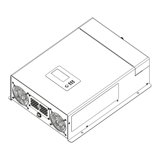
2 FEATURES This section identifies the default settings and the hardware features of the Freedom XC 2000 - 230V Inverter/Charger. This section includes: AC and DC Panel Display Panel Side Panel 975-0821-01-01... -
Page 22: Ac And Dc Panel
AC and DC Panel AC and DC Panel WARNING ELECTRICAL SHOCK HAZARD Use a torque screwdriver to tighten the captive nut panel screw to 0.56 N-m torque of force to ensure a proper earth connection and a required tool access to the wiring compartment. Failure to follow these instructions can result in death, serious injury, or equipment damage. - Page 23 AC and DC Panel Item Description WARNING DC terminal opening for routing (–) negative DC cable. ELECTRICAL SHOCK HAZARD DC terminal opening for routing (+) positive DC cable. Use a torque screwdriver to tighten the bolt on the DC earth lug to a torque of 2.6 N-m of force. LED alert indicator for reverse DC polarity.
-
Page 24: Display Panel
Display Panel Display Panel Table 2 Display Panel Features Item Description Display panel displays status information on the screen. It is comprised of a display screen, LEDs, and buttons. Multi-function LCD screen shows status information and error codes. INPUTBATTTEMP OUTPUTBATTLOAD ERROR BYPASS Status LEDs indicate the mode of operation. -
Page 25: Side Panel
Side Panel Side Panel Table 3 Side Panel Features Item Description Captive nut panel screw holds the wiring compartment cover in place. See WARNING on page 11. Wiring compartment cover protects the wiring compartment from debris and keeps the cables secure. Using the captive nut panel screw, the cover can be opened and lifted out during wiring. - Page 26 This page is intentionally left blank. [2]...
-
Page 27: Installation
INSTALLATION Please read this section for safety information and installation instructions regarding your Freedom XC. This section includes: Before You Begin the Installation Installation Codes Installation Tools and Materials Basic Installation Procedures Step 1: Designing the Installation Step 2: Choosing a Location for the Unit Step 3: Mounting the Unit Step 4: Connecting the AC Input Wires Step 5: Connecting AC Output to an Existing AC Circuit... -
Page 28: Before You Begin The Installation
Before You Begin the Installation Before You Begin the Installation Codes Governing installation codes vary depending on the specific Installation location and application of the installation. It is the installer’s responsibility to ensure that all applicable WARNING installation requirements are met. ELECTRICAL SHOCK AND FIRE HAZARD All wiring should be done by qualified personnel to ensure compliance with all applicable installation codes and... -
Page 29: Installation Tools And Materials
Before You Begin the Installation Installation Tools and Materials You will need the following to install the Freedom XC: Wire stripper Mounting (M2.5) screws or bolts Phillips torque screwdriver Torque wrench for DC terminals (13mm socket wrench) AC cable (that is, two-conductor-plus-earth cable), sized appropriately for load and application PG16 (or PG21) strain relief clamps (for the AC cable clamp holes) - Page 30 This page is intentionally left blank. [2]...
-
Page 31: Basic Installation Procedures
Basic Installation Procedures Basic Installation Procedures This section provides sample installation information as a guide for your installation. For your convenience, the overall procedure is divided into these main steps: Step 1: Designing the Installation Step 2: Choosing a Location for the Unit Step 3: Mounting the Unit Step 4: Connecting the AC Input Wires Step 5: Connecting AC Output to an Existing AC Circuit 31... -
Page 32: Step 1: Designing The Installation
Basic Installation Procedures Figure 5 Typical Recreational Vehicle and Fleet Vehicle Step 1: Designing the Installation Installation Most Freedom XC installations share common components, and some of these are briefly described in Step 1: Designing the Installation. Figure 5 shows some components and their relationship to each other in a typical recreational vehicle or fleet vehicle installation. - Page 33 Basic Installation Procedures AC Mains Power The branch-rated circuit breaker or fuse (connected AC Input through hard wiring) that is used to supply the A source of 230 VV 50Hz sine wave alternating current provides Freedom XC must be rated at no more than 30A energy to pass power through to AC loads.
- Page 34 Basic Installation Procedures applicable to your installation. Table 4 gives some examples of wiring sizes. These examples are based on using a two- AC Distribution Panels conductor-plus-earth copper cable rated at 60 °C, and assuming Most systems incorporate distribution centers both ahead of the an ambient temperature of up to 30 °C.
- Page 35 Basic Installation Procedures 3. Using a Phillips torque screwdriver, attach the bonding AC Output Neutral Bonding Option (Earth screw to the AC Out Neutral-to-Earth Bond hole. Relay Function) 4. Tighten the bonding screw to 0.85 N-m maximum torque. The earth relay function allows you to connect the neutral AC Earthing conductor (N) of the inverter output circuit to the safety earth As per IEC/EN 62477-1, for all permanently connected...
- Page 36 Basic Installation Procedures DC Cabling IMPORTANT: Using the correct cable size is critical to achieving the rated performance of the Freedom XC unit. When starting a This includes all the cables and connectors between the batteries, heavy load the Freedom XC can draw current surges from the the DC disconnect and over-current protection device, and the battery of up to 250A.
- Page 37 Basic Installation Procedures Batteries The Freedom XC uses 12 VZ battery banks. Every Freedom XC system is recommended to have a deep-cycle battery (house) or group of batteries with a total capacity of 100 Ah or more which provides the DC current that the Freedom XC converts to AC. 975-0821-01-01...
-
Page 38: Step 2: Choosing A Location For The Unit
Basic Installation Procedures Cool. Normal air temperature should be between -20 °C and Step 2: Choosing a Location for the 40 °C—the cooler the better, for increased efficiency and Unit product life extension. Ventilated. Allow at least 12 cm of clearance at the wiring access (AC and DC) end of the Freedom XC allowing air WARNING intake flow through the fans. -
Page 39: Step 3: Mounting The Unit
Basic Installation Procedures Figure 7 Approved Mounting Orientations Step 3: Mounting the Unit To mount the Freedom XC: 1. Remove the Freedom XC from its shipping container, verify that all components are present, and record relevant product information on Information About Your System on page ii. 2. - Page 40 Basic Installation Procedures Connecting the Equipment Earth Earthing Locations You must connect the equipment earth lug to an earthing point— usually the vehicle’s chassis or DC negative bus earth—using WARNING recommended copper wire (if insulated then green insulation with or without one or more yellow stripes) or larger. ELECTRIC SHOCK HAZARD Make sure to tighten the bolt on the DC earth lug to a torque of Never operate the Freedom XC without properly connecting the...
-
Page 41: Step 4: Connecting The Ac Input Wires
Basic Installation Procedures AC Wiring Connectors Step 4: Connecting the AC Input Wires Where applicable, connect AC wires with crimp-on splice connectors. The amount of insulation you strip off individual wires WARNING will be specified by the connector manufacturer and is different for different types of connectors. - Page 42 Basic Installation Procedures AC wiring must be sized appropriately using conductors with NOTICE insulation rated at least 75 °C to carry full load current on the input and output AC circuits in accordance with the electrical codes or REVERSE POLARITY DAMAGE regulations applicable to your installation.
- Page 43 Basic Installation Procedures Figure 10 Routing the AC input wires WARNING ELECTRIC SHOCK HAZARD Use a screwdriver to loosen the captive nut panel screw. Failure to follow these instructions can result in death, serious injury, or equipment damage. Figure 9 Loosening the captive nut panel screw sub-step a on page 30 sub-step b on page 30 sub-step c on page 30...
- Page 44 Basic Installation Procedures 8. Connect each AC wire into its corresponding terminal on the no-tool cage clamp terminal block. a. Lift the terminal lever (as shown in the previous figure). b. Insert the wire fully into the open slot. c. Lower the terminal lever to secure the wire in the slot. 9.
-
Page 45: Step 5: Connecting Ac Output To An Existing Ac Circuit
Basic Installation Procedures Step 5: Connecting AC Output to an NOTICE Existing AC Circuit EQUIPMENT DAMAGE Do not connect any AC source (such as a generator or utility WARNING power) to the AC output wiring of the Freedom XC. The Freedom XC will not operate if its output is connected to ELECTRIC SHOCK AND FIRE HAZARDS AC voltage from a source, and potentially hazardous or damaging conditions may occur. - Page 46 Basic Installation Procedures 2. Install the required circuit breaker in the inverter/charger AC Output Connections distribution panel receiving AC power from the Figure 11 Routing and connecting the AC output wires inverter/charger. 3. Remove the wiring compartment cover, if not already done from AC Output Connections on page 32.
- Page 47 Basic Installation Procedures 9. Tighten the strain relief clamp to secure the wires. 10. Replace the wiring compartment cover (using a #2 (3.5mm) Phillips torque screwdriver - see WARNING), if you are finished with connecting all the AC wires in the unit. WARNING ELECTRICAL SHOCK HAZARD Use a torque screwdriver to tighten the captive nut panel screw to...
-
Page 48: Step 6: Connecting The Dc Cables
Basic Installation Procedures Follow the procedure given below to connect the battery leads to Step 6: Connecting the DC Cables the terminals on the DC end. The cables should be as short as possible and large enough to handle the required current, in NOTICE accordance with the electrical codes or regulations applicable to your installation. - Page 49 Basic Installation Procedures 6. Strip 13 to 19 mm of insulation from each cable end that will To make the DC connections: be connected to the inverter/charger. The amount stripped 1. Make sure the inverter/charger is off and no AC or DC is off will depend on the terminals chosen.
- Page 50 Basic Installation Procedures Figure 12 DC Cable Connections WARNING ELECTRICAL SHOCK HAZARD Tighten the nuts on the DC terminals properly. Loose connections cause excessive voltage drop and may cause overheated wires and melted insulation. Do not over-tighten the nut on the DC input terminals because damage to the DC input terminals may result.
- Page 51 Basic Installation Procedures 15. Replace the wiring compartment cover by tightening the WARNING captive nut panel screw. See the following electrical shock hazard warning. FIRE HAZARD WARNING Do not complete the next step if flammable fumes are present. Explosion or fire may result if the disconnect/battery selector switch ELECTRICAL SHOCK HAZARD is not in the off position.
- Page 52 Basic Installation Procedures DC Earthing For DC voltage systems under 50 VZ in an RV installation, an 8.36mm Regulatory copper bonding conductor would be acceptable for the inverter/charger enclosure To connect the DC earth: references earth bonding only. The "house" battery system must, however, be earth bonded. 1.
-
Page 53: Step 7: Connecting To Port(S) On The Freedom Xc
Basic Installation Procedures Figure 13 Ignition signal (ACC) input terminal Step 7: Connecting to Port(s) on the Freedom XC Connecting to ACC Signal With the ACC, the Freedom XC can be wired to inhibit inverter operation in the absence of a vehicle’s (or vessel's) +12VZ ignition control signal. - Page 54 Basic Installation Procedures Description of Ignition Control Features Connecting to the Remote Port For information about the features and instructions on changing The Freedom XC can accommodate the Freedom X Remote the ignition control features, see Operation on page 45. Panel with cable (PN: 808-0817-01) (sold separately;...
-
Page 55: Step 8: Testing Your Installation
Basic Installation Procedures Testing in Battery Mode Step 8: Testing Your Installation To test the Freedom XC: 1. For hard wired installations, ensure shore power is not WARNING present. 2. Press the Power button to turn the inverter/charger on. ELECTRIC SHOCK HAZARD The green LED indicating Battery mode (Inverter mode) Pressing the Power button to turn the Freedom XC inverter to turns on and the LCD screen displays the BATT. - Page 56 Basic Installation Procedures Testing in Grid Mode To test the Freedom XC: With the test load from the previous test still connected and operating, connect the shore power source. The Freedom XC transfers the test load to shore power. The green LED indicating grid mode turns on and the LCD screen displays the AC MODE icon.
-
Page 57: Marine Installation
Marine Installation Marine Installation Figure 14 Typical Marine Installation Figure 14 illustrates a typical marine installation with the following components: DC Equipment earth – Engine negative bus / DC earth bus Freedom XC DC fuse/disconnect/DC circuit breaker 12V deep cycle battery [house] Battery isolator DC alternator To engine... -
Page 58: Drip Shield Installation
Marine Installation Drip Shield Installation Figure 15 Drip shields To install the drip shields: The drip shields help to protect the unit from dripping or splashing 1. Gather the four screws needed liquids, which will cause a shock hazard when moisture comes in to fasten a single drip shield to a contact with electrical circuits in the unit. -
Page 59: Operation
4 OPERATION This section includes descriptions of the different modes and Operating Several Loads at Once settings of the Freedom XC 2000 - 230V Inverter/Charger. This Operating Several Loads at Once section includes: Turning the Audible Alarm ON or OFF Freedom XC Display Panel Operating in Grid Mode Status LED Indicators... -
Page 60: Freedom Xc Display Panel
Freedom XC Display Panel Freedom XC Display Panel Status LED Indicators Figure 17 Display Panel Indicator Definition Solid green. Indicates grid mode in which shore power is available and passing through to the loads and charging the INPUTBATTTEMP OUTPUTBATTLOAD battery. -
Page 61: Function Buttons
Freedom XC Display Panel Function Buttons LCD Screen The LCD Screen changes depending on the operating mode of the Button Definition inverter/charger. Return to default screen or exit setting mode. Figure 18 Parts of the LCD Screen Scroll to next screen or next selection. Press and hold for 3 s to scroll back one step. -
Page 62: Lcd Screen Icons
Freedom XC Display Panel LCD Screen Icons Icon Definition The load icon is displayed if there is Icon Definition voltage available at the AC output. AC input and output indicator. The wrench icon underneath a number is The bar represents load consumption displayed during configuration mode. -
Page 63: Viewing Information During Battery Mode
Viewing Information During Battery Mode Viewing Information During Info and Setting LCD Screen Battery Mode The LCD screen displays information related to battery mode operation. Screen 2 of 4 - Press the Scroll button to move from screen to screen. AC Output Press and hold for 3 s to go back one step. - Page 64 Viewing Information During Battery Mode Info and Setting LCD Screen Screen 4 of 4 - Firmware version Firmware version = U1 1.01 Freedom XC 2000 - 230V Owner's Guide...
-
Page 65: Viewing Information During Grid Mode
Viewing Information During Battery Mode Viewing Information During Grid Info and LCD Screen Mode Setting 1. The LCD screen displays information related to AC bypass or charger operation. 2. Press the Scroll button to move from screen to screen. 3. Press to return to the home screen. - Page 66 Viewing Information During Battery Mode Info and Info and LCD Screen LCD Screen Setting Setting Screen 2 of Screen 4 of Battery AC input Voltage/ voltage/AC Charging input Current frequency battery voltage = 12.5VZ, charging current = 60A input voltage = 230VV, input frequency = 50Hz Screen 3 of Screen 5 of AC input...
-
Page 67: Adjusting Settings In Configuration Mode
Adjusting Settings in Configuration Mode Adjusting Settings in To change the default value to a different value and to save the change permanently: Configuration Mode NOTICE , Scroll , and buttons can be used to cycle through the various settings: REQUIRED OPERATION 1. - Page 68 Adjusting Settings in Configuration Mode 5. Press the button to confirm the change. 6. Repeat the previous steps to set other settings. 7. Press the button to exit the Configuration mode. IMPORTANT STEPS 8. Keep the Freedom XC powered with a DC source (battery). 9.
-
Page 69: Settings
Adjusting Settings in Configuration Mode Settings Setting Default Range of Setting Name Description Number Value Values Inverter Ignition Control See Description of Ignition Control Features on page 40. The voltage setting value can be adjusted by 0.1 increments. The 10.5 10.0 to 12.8 LBCO Voltage inverter is able to recover automatically at LBCO voltage + 2.0 V... - Page 70 Adjusting Settings in Configuration Mode Setting Default Range of Setting Name Description Number Value Values After changing the output frequency setting, turn the unit off and Output Frequency then on again, in order for the change to take effect. Output Voltage In VV Inverter Output Power The wattage setting value can be adjusted by 100-W increments.
- Page 71 Adjusting Settings in Configuration Mode Setting Default Range of Setting Name Description Number Value Values The inverter shuts down when there is an over temperature, overload, and short circuit condition. Selecting ATO (auto-restart) At0(auto- will allow the inverter/charger to recover automatically from a Inverter Shutdown restart) shutdown up to three times maximum.
- Page 72 Adjusting Settings in Configuration Mode Setting Default Range of Setting Name Description Number Value Values Charger Current 5 to 80 (Freedom XC 2000 - The current setting value can be adjusted by 5A increments. 230V) OFF(OFF) Charger Ignition Control See Description of Ignition Control Features on page 40. AT0 (Auto-ON) Equalize Charging for ENA (enable)
-
Page 73: Operating In Battery Mode
Operating in Battery Mode Operating in Battery Mode Turning Inverter Operation ON and OFF There are two ways to operate the Freedom XC’s inverter The Freedom XC is in Battery Mode (also called Inverter Mode) function. when all the following conditions exist: 1. -
Page 74: Power Save Timer
Operating in Battery Mode Power Save Timer Checking Battery Status The Power Save Timer is an adjustable countdown timer from 1 to During inverter operation (in battery mode), you can check the 25 h (25 h is the default) that automatically shuts down inverter battery status by observing the battery capacity indicator on the operation to reduce battery discharge and preserve battery life. -
Page 75: Operating Several Loads At Once
Operating in Battery Mode 2. If the Inverter Ignition Control is set to auto-on, toggle the Operating Several Loads at Once ignition signal to clear the alarm and error. If you are going to operate several loads from the Freedom XC, 3. -
Page 76: Operating In Grid Mode
Operating in Grid Mode Operating in Grid Mode Battery Types The Freedom XC 2000 - 230V Inverter/Charger charges flooded (or wet) lead-acid, Gel, AGM (absorbed glass mat), custom, and Battery Charger Functions lithium iron phosphate (LFP) Xantrex batteries. When AC power is available, the Freedom XC can operate as a Flooded (or wet) batteries have removable battery caps for 12-VZ battery charger. - Page 77 Operating in Grid Mode There is a fourth stage, equalization, which is initialized manually NOTICE as it is only performed occasionally and only on flooded (or wet) batteries. BATTERY DAMAGE The charging cycle is a multistage (three-stage) process. Do not mix battery types. The Freedom XC can only select one battery type setting for all batteries connected to its bank.
- Page 78 Operating in Grid Mode The Freedom XC has been in absorption for the Bulk Stage programmed maximum absorption time limit. The default is Bulk charge is the first stage in the charging process and provides 6 h. the batteries with a controlled, constant current. Once the battery NOTE: If there are DC loads on the batteries, the charger’s voltage rises to the absorption voltage threshold, the charger current may never decrease to a level to initiate the next stage of...
- Page 79 Operating in Grid Mode Equalize Charging Table 11 Preset Float Voltage Settings Many battery manufacturers recommend periodic equalize Battery Type Preset Float Voltage charging to counter cell charge imbalance and capacity-robbing Flooded 13.5 electrolyte stratification. Equalizing helps to improve battery performance and lifespan by encouraging more of the battery 13.8 material to become active.
-
Page 80: Custom Battery Settings Menu
Operating in Grid Mode Figure 20 Equalize charging Custom Battery Settings Menu NOTICE REVERSE POLARITY To avoid damaging your batteries during charging or equalization, consult your battery manufacturer and associated documentation before setting a custom battery type. Failure to follow these instructions can result in equipment damage. -
Page 81: Operating During Transition Between Grid Mode And Battery Mode
Operating During Transition Between Grid Mode and Battery Mode Operating During Transition Transitioning from Grid Mode to Battery Mode Between Grid Mode and Battery When the unit is operating in grid mode and shore power is lost, Mode the Freedom XC has less than 20 milliseconds (default) to switch The Freedom XC’s advanced power management is capable of to operating in battery mode (if the Power button is pressed in the transitioning power from an AC mains to DC source within a... -
Page 82: Operating Limits
Operating Limits Operating Limits Power Output The Freedom XC can deliver up to 2000 W of continuous utility These are the operating limits of the Freedom XC: grade sine wave AC power. The wattage rating applies to resistive Power Output loads such as incandescent lights. Input Voltage Overload Conditions High Surge Loads... -
Page 83: Input Voltage
Operating Limits Input Voltage Operating Battery Comment The allowable Freedom XC input battery voltage ranges are Condition Voltage shown in the following table: The buzzer sounds a single 1 s Table 12 Input battery voltage range low battery alarm beep and the LCD screen shows error code Operating Battery... -
Page 84: Overload Conditions
Operating Limits Overload Conditions Operating Battery Comment There are two kinds of overload conditions – an overload warning Condition Voltage and an overload shutdown. The display shows error code Overload When the Freedom XC’s AC load is approximately 100 W E02 alternating with the battery Warning below the overload shutdown limit of rated watts, the voltage. -
Page 85: High Surge Loads
Operating Limits High Surge Loads Some induction motors used in freezers, pumps, and other motor- operated equipment require high surge currents to start. The Freedom XC may not be able to start some of these motors even though their rated steady state current draw is within the inverter/charger’s limits. - Page 86 This page is intentionally left blank. [2]...
-
Page 87: Routine Maintenance
5 ROUTINE MAINTENANCE Regular maintenance is required to keep your Freedom XC operating properly. This section includes: Maintaining the Freedom XC Unit 975-0821-01-01... -
Page 88: Maintaining The Freedom Xc Unit
Maintaining the Freedom XC Unit Maintaining the Freedom XC Unit WARNING ELECTRICAL SHOCK HAZARD Turning the Power k button to Standby does not disconnect DC battery power from the Freedom XC. You must disconnect from all power sources before working on any circuits connected to the unit. Failure to follow these instructions can result in death, serious injury, or equipment damage. -
Page 89: Troubleshooting
6 TROUBLESHOOTING This section will help you narrow down the source of any problem you encounter. Before contacting customer service, please work through the steps listed in Pre-service Checklist on page 76. This section includes: Pre-service Checklist Warning Messages Troubleshooting Reference Inverter Applications Resistive Loads Motor Loads... -
Page 90: Pre-Service Checklist
Pre-service Checklist Whether any extreme ambient conditions existed at Pre-service Checklist the time (temperature, vibrations, moisture, etc.) 3. If your Freedom XC is not displaying an error code, check the following to make sure the present state of the WARNING installation allows proper operation: Is the inverter/charger located in a clean, dry, ELECTRICAL SHOCK HAZARD... -
Page 91: Warning Messages
Warning Messages Warning Messages Warning messages in the form of audible alarms and error codes that appear on the LCD screen to alert you to an impending system change. Warnings do not affect operation. With the exception of the error codes displayed on the screen, only the audible alarm can be turned ON or OFF. - Page 92 Warning Messages Table 13 Error codes displayed on the LCD screen Error Code Condition Mode Action Low battery voltage shutdown is imminent Check battery status and recharge if necessary. depending on the setting, Battery mode Check for proper DC cable sizing. see Maintaining the (inverting) Check for loose connections and tighten if necessary.
- Page 93 Warning Messages Error Code Condition Mode Action Reduce the loads connected to the AC outlet of the unit. Check that the ventilation grille is not blocked. Over-temperature alarm Battery mode Check for ambient temperature and move the unit to a cooler and fan lock alarm (inverting) location whenever possible.
-
Page 94: Troubleshooting Reference
Troubleshooting Reference Troubleshooting Reference WARNING ELECTRICAL SHOCK HAZARD Do not disassemble the Freedom XC. It does not contain any user- serviceable parts. Attempting to service the unit yourself could result in an electrical shock or burn. Failure to follow these instructions can result in death, serious injury, or equipment damage. - Page 95 Troubleshooting Reference Table 14 Troubleshooting reference Problem Possible Cause Solution Alarm does not sound when an error is Alarm is turned OFF. See Turning the Audible Alarm ON or OFF on page 61 encountered. and follow instructions to turn the alarm buzzer on again.
- Page 96 Troubleshooting Reference Problem Possible Cause Solution No output voltage is shown in the LCD Circuit breaker on the AC load Reset the circuit breaker or check the AC output screen but the green status LED for panel or AC output disconnect has disconnect circuits.
- Page 97 Troubleshooting Reference Problem Possible Cause Solution No output voltage. The status LED is Ignition lock (ACC) signal is not If the ignition control feature is in use, ensure the not lighting up. present. vehicle’s ignition is On and the ignition control switch on the front of the Freedom XC unit is On (|).
-
Page 98: Inverter Applications
Inverter Applications Inverter Applications Motor Loads Induction motors (that is, motors without brushes) require two to The Freedom XC performs differently depending on the AC loads six times their running current on start up. The most demanding connected to it. If you are having problems with any of your loads, are those that start under load, for example, compressors and read this section. -
Page 99: Problem Loads
Inverter Applications When the Freedom XC is in power save mode, it may fail to start Problem Loads some loads even though the rated wattage on the load is more Very Small Loads If the power consumed by a device is less than 25 W. - Page 100 This page is intentionally left blank. [2]...
-
Page 101: Specifications
SPECIFICATIONS This section summarizes the hardware and electrical specifications of the Freedom XC 2000 - 230V Inverter/Charger. Physical Specifications Environmental Specifications System Specifications Regulatory Approvals NOTE: Specifications are subject to change without prior notice. 975-0821-01-01... -
Page 102: Physical Specifications
Physical Specifications Physical Specifications Environmental Specifications Table 15 Physical specifications Table 17 Environmental specifications Freedom XC 2000 - 230V Freedom XC 2000 - 230V Ambient Temperature: 390mm × 275mm × 102mm without flanges. L × W × H Operating Temperature Range -20 –60 ºC, with output derated 390mm ×... -
Page 103: System Specifications
System Specifications System Specifications Table 19 DC input for inverting Freedom XC 2000 - 230V Table 18 System specifications 10–17.0 V Z Operating voltage range Freedom XC 2000 - 230V Maximum non-operating voltage 25.2 V Z Transfer relay rating (A 30A V 12.0 V Z Nominal voltage Transfer time (ms... -
Page 104: Regulatory Approvals
Regulatory Approvals Regulatory Approvals Table 21 AC input for charging Freedom XC 2000 - 230V Table 23 Regulatory approvals Operating voltage range 170–280 VV Freedom XC 2000 - 230V Safe non-operating voltage up to 300 VV Compliance with CE Marking: range Low Voltage Directive 5.6 A V Full load maximum current (2014/35/EU) - Page 105 This page is intentionally left blank. [2]...
- Page 106 http://www.xantrex.com/ (Toll Free USA/Canada) +1 800 670 0707 (Outside USA/Canada) +1 408 987 6030 975-0821-01-01 Rev E Printed in:...
Need help?
Do you have a question about the Xantrex Freedom XC 2000 - 230V and is the answer not in the manual?
Questions and answers