Table of Contents
Advertisement
Quick Links
Advertisement
Table of Contents
Troubleshooting

Related Manuals for Mission Critical Xantrex Freedom SW-RVC


Summary of Contents for Mission Critical Xantrex Freedom SW-RVC
- Page 1 INVE BLED RNIN RGIN R FAU T CHA RNIN Owner’s Guide Product Model Number Freedom SW-RVC Inverter/Charger 815-3012-02...
- Page 2 Copyright © 2022 Xantrex LLC. All Rights Reserved. All trademarks are owned by Xantrex LLC and its affiliates. Exclusion for Documentation UNLESS SPECIFICALLY AGREED TO IN WRITING, SELLER (A) MAKES NO WARRANTY AS TO THE ACCURACY, SUFFICIENCY OR SUITABILITY OF ANY TECHNICAL OR OTHER INFORMATION PROVIDED IN ITS MANUALS OR OTHER DOCUMENTATION; (B) ASSUMES NO RESPONSIBILITY OR LIABILITY FOR LOSSES, DAMAGES, COSTS OR EXPENSES, WHETHER SPECIAL, DIRECT, INDIRECT, CONSEQUENTIAL OR INCIDENTAL, WHICH MIGHT ARISE OUT OF THE USE OF SUCH INFORMATION.
- Page 3 ABOUT THIS GUIDE Purpose Audience The purpose of this Owner’s Guide is to provide explanations and The guide is intended for users and operators of the Freedom SW- procedures for operating, maintaining, and troubleshooting a RVC Inverter/Charger. Freedom SW-RVC Inverter/Charger for recreational vehicle and The guide (Installation Guide (document number: 975-1057-01- commercial applications.
-
Page 4: Important Safety Instructions
IMPORTANT SAFETY INSTRUCTIONS ’ READANDSAVE THIS WNER UIDE FORFUTURE REFERENCE DANGER This chapter contains important safety instructions for the DANGER indicates a hazardous situation which, if not avoided, will result in death or serious injury. Freedom SW-RVC Inverter/Charger (Freedom SW-RVC). Each time, before using the Freedom SW-RVC, READ ALL instructions and cautionary markings on or provided with the WARNING... -
Page 5: Safety Information
Safety Information Safety Information load. Turning the inverter/charger to Standby using the Power button on the panel will not reduce an electrical shock hazard. 8. The inverter/charger must be provided with an equipment- 1. Before using the inverter/charger, read all instructions and ground. - Page 6 Safety Information DANGER DANGER FIRE AND BURN HAZARD ELECTRIC SHOCK HAZARD • Do not expose the Freedom SW-RVC to rain, snow, or spray water. • Do not cover or obstruct the air intake vent openings and/or install in a zero- clearance compartment. •...
-
Page 7: Precautions When Working With Batteries
Precautions When Working With Batteries Precautions When Working With DANGER Batteries EXPLOSION HAZARD IMPORTANT: Battery work and maintenance must be done by • Charge only properly rated (such as 12 V) lead-acid (GEL, AGM, Flooded, or qualified personnel knowledgeable about batteries to ensure lead-calcium) or other approved rechargeable batteries because other compliance with battery handling and maintenance safety battery types may explode. -
Page 8: Precautions When Preparing To Charge
Precautions When Preparing to Charge NOTES: Precautions When Preparing to 1. Mount and place the Freedom SW-RVC Inverter/Charger unit Charge away from batteries in a well ventilated compartment. 2. Always have someone within range of your voice or close enough to come to your aid when you work near a lead-acid WARNING battery. -
Page 9: Precautions When Placing The Unit
Precautions When Placing the Unit Precautions When Placing the Regulatory Unit The Freedom SW-RVC is certified to appropriate US and Canadian standards. For more information see Specifications on page 68. The Freedom SW-RVC is intended to be used for recreational NOTICE vehicle and commercial applications. -
Page 10: Emi Information To The User
EMI Information to the User EMI Information to the User End of Life Disposal This equipment has been tested and found to comply with the limits The Freedom SW-RVC Inverter/Charger is designed with for a Class B digital device, pursuant to part 15 of the FCC and ISED environmental awareness and sustainability in mind. -
Page 11: Table Of Contents
CONTENTS Important Safety Instructions Mechanical Features Safety Information Freedom SW-RVC Front and Side Panels Precautions When Working With Batteries Freedom SW-RVC AC and DC Side Panel Operation Precautions When Preparing to Charge Precautions When Placing the Unit Start Up Behavior Regulatory Inverter Operation Using the Front Panel EMI Information to the User... - Page 12 Equalize Charging Routine Maintenance Maintaining the Freedom SW-RVC Unit Troubleshooting Troubleshooting the Freedom SW-RVC Inverter Applications Resistive Loads Motor Loads Problem Loads Specifications Freedom SW-RVC Owner's Guide...
-
Page 13: Introduction
1 INTRODUCTION Congratulations on your purchase of the Freedom SW-RVC Materials List Inverter/Charger (Freedom SW-RVC). The Freedom SW-RVC The Freedom SW-RVC ships with the following items: has been designed to give you premium power, ease of use, and outstanding reliability. one Freedom SW-RVC unit Installation Guide Please read this chapter to familiarize yourself with the... -
Page 14: Key Features
Key Features As a charger, it has high output, multistage charging Key Features capability minimizing charging time. The Freedom SW-RVC is a true sine wave inverter/charger that Capable of operating from 50 Hz and 60 Hz power source can be used for recreational vehicle and commercial applications. by extending AC qualification frequency range. -
Page 15: Key Features Explained
Key Features Key Features Explained Manual Over a period of time, the cells in a flooded Equalization battery can develop uneven chemical Built-in Charge For the unit to perform at the highest level, states. This can result in a weak Formulas the batteries must be charged correctly. - Page 16 Key Features Freedom SW-RVC has a power Load Management The Freedom SW-RVC has a built-in share feature which prioritizes your transfer relay that connects your inverter AC loads by reducing the charge output or AC input from the utility grid or current in an attempt to limit the total generator to your loads.
-
Page 17: Stacking
Key Features Stacking Stack Charging Supports stacking of two inverter/chargers to increase capacity. Two Freedom SW-RVCs synchronize charging stages to ensure This also requires the installer to select a Master and Slave in efficient charging of the battery bank. When a single unit order for the inverters to stack. -
Page 18: Generator Assist
Basic Protection Features Basic Protection Features Generator Assist The Freedom SW-RVC inverter/chargers can operate in tandem The Freedom SW-RVC has the following protection features: with a generator (or shore power) to temporarily assist power Over temperature shutdown for critical components such as loads with large start-up demands such as air conditioners, water the transformer and the power board pumps etc. -
Page 19: Freedom Sw-Rvc Supplied Accessories
Freedom SW-RVC Supplied Accessories Freedom SW-RVC Supplied Item Description Two DC terminal covers are supplied to prevent accidental Accessories contact with the DC cable connectors after installation. The red cover is for the positive cabling terminal, and the black cover is for Figure 2 Supplied Accessories the negative cabling terminal. -
Page 20: Other Accessories
Freedom SW-RVC Supplied Accessories Other Accessories # Product/Accessory Product Number/s 1 3-ft network cable (0.9 m) 809-0935 2 25-ft network cable (7.6 m) 809-0940 3 75-ft network cable (22.9 m) 809-0942 4 Inverter drip shield 808-9004 Product/Accessory (Not Shown) Product Number/s Freedom SW-RVC On/Off Switch 808-9002 GFCI receptacles... -
Page 21: Mechanical Features
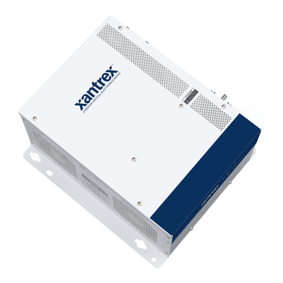
2 MECHANICAL FEATURES RNIN INVE BLED RGIN R FAU T CHA RNIN Figure 3 Freedom SW Front and Side Panels Front and Side Panels AC and DC Side Panels 975-1056-01-01... -
Page 22: Freedom Sw-Rvc Front And Side Panels
Freedom SW-RVC Front and Side Panels Freedom SW-RVC Front and Figure 4 Isometric View of the Front Panel and Fans Side Panels Before you begin to operate the Freedom SW-RVC, review the front panel features shown in Figure 4 and described in the next table. - Page 23 Freedom SW-RVC Front and Side Panels Figure 5 Isometric View of the Front Panel and AC/DC Side Panel Item Description RV-C INTERFACE ports are used to connect RV-C devices including a RV-C system device controller, if available. STACKING port is used to connect two inverter/chargers together for stacked operation.
-
Page 24: Freedom Sw-Rvc Ac And Dc Side Panel
Freedom SW-RVC AC and DC Side Panel Freedom SW-RVC AC and DC Item Description Side Panel Negative (–) DC terminal (black). Use a qualified personnel for connecting cables. The DC side of the Freedom SW-RVC has the DC equipment Positive (+) DC terminal (red). Use a qualified personnel for ground lug, the positive (+) battery terminal, and the negative (-) connecting cables. -
Page 25: Operation
3 OPERATION Start Up Behavior Enable versus When a function is enabled, it is allowed to Disable occur but other conditions may have to be met When the Freedom SW-RVC is powered up or has been reset, all before the function actually works. For of the front panel LEDs turn on and remain on for a minimum of example, the charger function on the Freedom five seconds. -
Page 26: Inverter Operation Using The Front Panel
Inverter Operation Using the Front Panel The INVERTER ENABLED LED turns on. The inverter Inverter Operation Using the should run the load using battery power. Front Panel 6. To test the charger, reconnect the AC input power to allow AC to the AC input. The AC In/Charging LED should start IMPORTANT: flashing after a brief delay. - Page 27 Inverter Operation Using the Front Panel Table 1 Faults and A fault affects the operation of the unit. A Front Panel LEDs Warnings manual fault requires user intervention by clearing the condition and then pressing the Action (or CLEAR FAULT RESET button on the Color Status inverter/charger’s front panel.
-
Page 28: Operating Limits For Inverter Operation
Operating Limits for Inverter Operation Operating Limits for Inverter Difficulty on The inverter/charger should be able to operate starting loads all AC loads rated at or below its power rating. Operation Some high horsepower induction motors used in pumps and other motor-operated equipment Temperature The Freedom SW-RVC inverter/charger will require very high surge currents to start, and the... -
Page 29: Operating Limits For Charger Operation
Operating Limits for Charger Operation Operating Limits for Charger AC Frequency The charger can also be configured to accept and operate from a wide AC source frequency Operation of 40–68 Hz. Therefore, the Freedom SW-RVC can charge your batteries even when incoming By default, the maximum charger output current is the rated AC voltage is less than ideal. - Page 30 Operating Limits for Charger Operation For example, if the AC input of the Freedom SW-RVC is from an AC panel with a 30-amp breaker, the AC1 Breaker setting should be selected as 30 amps. Based on this, the charger will control the charge current so that the total current draw is equal to or less than 24 amps in this case.
-
Page 31: Configuring The Freedom Sw-Rvc
Configuring the Freedom SW-RVC Configuring the Freedom SW- Equalize Initiates the battery equalization process. See Equalization Procedure on page 33 to enable the procedure. Default value is Disabled. Switches between Operating and Safe modes. Desired This section contains information about all configurable settings Default value is Operating. -
Page 32: Using Load Sense
Configuring the Freedom SW-RVC Using Load Sense NOTE: The Slave unit continuously monitors the output of the Master unit. Why use Load Sense? If the Master unit has more than 60% of the rated load (for example, Load Sense allows the inverter to selectively power only items 1800 watts), the Slave unit will assist the Master and the two will that draw more than a certain amount of power, which can result in share the load equally. -
Page 33: Equalization Procedure
Configuring the Freedom SW-RVC Equalization Procedure NOTE: Load Sense, by function, cannot work with clocks and timers or To start equalizing the batteries, do one of the following: devices that need power 24 hours a day. Examples of devices Apply AC voltage and ensure that the inverter/charger with timers include video recorders, coffee makers with brew transfers AC and starts charging. -
Page 34: Changing Freedom Sw-Rvc Basic Settings
Configuring the Freedom SW-RVC Changing Freedom SW-RVC Basic WARNING Settings EXPLOSION HAZARD Temporary versus permanent Equalize charge flooded or vented batteries only. Hydrogen and oxygen gases are produced when batteries are equalize charged. The Freedom SW-RVC unit stores its configuration in its onboard Provide adequate ventilation and remove all sources of ignition to memory which holds configuration values even during power prevent explosion. - Page 35 Configuring the Freedom SW-RVC Table 3 Item Description Setting Defaults and Ranges Sets the percentage of the maximum DC output current that is Max Chg available to the charger. The maximum DC output current is 150 Model Freedom SW-RVC Rate Item Default If two Freedom SW-RVCs are charging the same battery bank, set...
-
Page 36: Changing Freedom Sw-Rvc Advanced Settings
Configuring the Freedom SW-RVC Inverter Settings Changing Freedom SW-RVC Under Inverter Settings you can control when the Freedom SW- Advanced Settings RVC starts and stops producing AC output. The advanced settings option gives you access to the full range of Table 5 Freedom SW-RVC settings, including everything displayed under Setting Defaults and Ranges... - Page 37 Configuring the Freedom SW-RVC Using the Low Battery Cut Out and Item Description LBCO Delay Settings LBCO Delay controls how long the inverter is allowed to operate at or The Low Batt Cut Out setting is the lowest battery voltage level LBCO below the Low Batt Cut Out level before turning off due to a low Delay...
- Page 38 Configuring the Freedom SW-RVC Charger Settings Table 8 With Charger Settings you can configure the Freedom SW-RVC Charger Settings Description to operate from your battery bank. Item Description Table 7 Sets the system battery chemistry and type: Flooded, AGM, Gel, Batt Setting Defaults and Ranges and Custom.
- Page 39 Configuring the Freedom SW-RVC Battery Charger Functions Item Description When AC power is available, the Freedom SW-RVC can operate Sets the maximum time spent in the absorption stage, before Absorb as a battery charger. Different battery types and chemistries transitioning to float or no float. Time require different charging voltage levels.
- Page 40 Configuring the Freedom SW-RVC Custom Battery Settings Custom Battery Settings can be viewed if Custom is selected as the Batt Type. You can adjust charging and equalization NOTICE voltage for batteries with specifications that fall outside the default settings for the battery types the Freedom SW-RVC offers. You EQUIPMENT DAMAGE can also adjust the temperature compensation constant for the Consult your battery manufacturer and associated documentation...
- Page 41 Configuring the Freedom SW-RVC ACIn Settings Item Description ACIn Settings configures the voltage and frequency limits for Sets the absorption voltage for a custom battery type. AC Input quantification range. These are the limits at which the Absorb Voltage Freedom SW-RVC considers input voltage qualified—that is, Sets the float voltage for a custom battery type.
- Page 42 Configuring the Freedom SW-RVC Gen Support Table 12 GEN Support is basically generator (and also shore power) ACIn Settings Description support for the Freedom SW-RVC that allows power to be Item Description automatically drawn from the batteries to assist an AC generator or shore power to support heavy loads (for example, loads that Sets the AC1 (Grid) breaker size, based on the size of the breaker exceed the available current from either a generator or shore...
- Page 43 Configuring the Freedom SW-RVC Stacking Configuration Setting Description Default Range Stacking configures the Freedom SW-RVC to operate as a part of Sets the generator or 4A to 24A a multi-unit installation. GenSup shore power load level at Amps When installing a stacked system, every setting on the Stacking which the Freedom SW- setting must be configured for each Freedom SW-RVC in the RVC supplies power...
- Page 44 Configuring the Freedom SW-RVC Resetting the Freedom SW-RVC to Default Settings The Restore Defaults command returns the Freedom SW-RVC to factory default settings. After using the Restore Defaults command, the Freedom SW-RVC is no longer configured for the power system. To restore Freedom SW-RVC default settings navigate to this device using the RV-C system device controller, if available.
-
Page 45: Battery Charging Reference
Battery Charging Reference Battery Charging Reference Battery Types Freedom SW-RVC charges Flooded (or wet) lead-acid, Gel, This section describes the multistage charging algorithm (formula) AGM (absorbed glass mat), and Custom batteries. of the Freedom SW-RVC. Flooded (or wet) batteries have removable battery caps for refilling with distilled water and testing the electrolyte. -
Page 46: Charge Algorithm Stages
Battery Charging Reference Charge Algorithm Stages Two-Stage Two-stage (or no float) mode differs from an charging ordinary three-stage charge mode in that it does Three-Stage If three-stage charging is enabled, the Freedom not continuously maintain the battery at float charging SW-RVC will charge batteries in a sequence voltage. - Page 47 Battery Charging Reference NOTE: Figure 7 Three-Stage Battery Charging Cycle When the charge cycle is interrupted, the charger will restart Bulk Stage Absorption Stage Float Stage Battery Voltage charging at the beginning of the multistage algorithm. Absorption Voltage Exit Current Threshold can be effectively disabled by Float Voltage 3-Stage Charge programming the amp-hour capacity to the minimum.
- Page 48 Battery Charging Reference Bulk Stage Absorption Stage Bulk charge is the first stage in the charging process and provides Absorption charge is the second stage of battery charging and the batteries with a controlled, constant current. Once the battery provides the batteries with a controlled, constant voltage. During voltage rises to the absorption voltage threshold, the charger this stage, the current drawn by the batteries slowly decreases.
- Page 49 Battery Charging Reference The Freedom SW-RVC transitions to the float stage if either one Float Stage of the following two conditions are met: Float charge maintains the batteries slightly above the self The charge current allowed by the batteries falls below the discharge voltage of the batteries.
-
Page 50: Two-Stage Charging Process
Battery Charging Reference Two-Stage Charging Process WARNING Two-stage (or no float) mode differs from an ordinary three-stage charge mode in that it does not continuously maintain the battery ELECTRIC SHOCK HAZARD at float voltage. Instead, the Freedom SW-RVC begins charging The battery voltage can increase above the float voltage when the battery in bulk mode whenever the battery voltage drops below using an external charging device such as PV arrays, wind... - Page 51 Battery Charging Reference Figure 8 Two-Stage Charging Cycle NOTE: Bulk Stage When the charge cycle is interrupted, the charger will restart Absorption Stage Battery charging at the beginning of the multistage algorithm. Voltage Absorption Voltage Exit Current Threshold can be effectively disabled by 2-Stage Charge programming the amp-hour capacity to the minimum.
-
Page 52: Equalize Charging
Battery Charging Reference When Equalize mode is enabled, the battery is charged from bulk Equalize Charging to absorption, and then to the equalize phase. The Freedom SW- NOTE: There is a fourth stage, equalization, which is initialized RVC will transition from the absorption phase to equalize if: manually as it is only performed occasionally and only on flooded the DC charge current is below 2% of the configured battery (or wet) batteries. - Page 53 Battery Charging Reference Figure 9 Equalize Charging Bulk Stage Absorption Stage Equalize Stage Battery Voltage Equalize Voltage Bulk Voltage Absorption Voltage Equalize mode Custom Charge Time Max Absorb Time - Dflt 3 hrs (adjustable 1 min - 8 hrs ) Battery Current Equalize Timer...
-
Page 54: Routine Maintenance
4 ROUTINE MAINTENANCE Maintaining the Freedom SW- RVC Unit WARNING ELECTRICAL SHOCK HAZARD Turning the Power k button to Standby does not disconnect DC battery power from the Freedom SW-RVC. You must disconnect from all power sources before working on any circuits connected to the unit. -
Page 55: Troubleshooting
5 TROUBLESHOOTING This section will help you narrow down the source of any problem guidelines carefully. you encounter. Is the inverter/charger located in a clean, dry, Before contacting customer service, please work through the steps adequately ventilated place? listed below. Are the battery cables adequately sized as recommended in the Installation guide? 1. -
Page 56: Troubleshooting The Freedom Sw-Rvc
Troubleshooting the Freedom SW-RVC Troubleshooting the Freedom Detected Fault There are three types of detected fault Types messages: automatic faults, manual faults, and SW-RVC escalating automatic faults. The following table describes how they differ in their behavior and The Freedom SW-RVC is designed with a number of protection how you can respond to them when they appear features to provide efficient operation. - Page 57 Troubleshooting the Freedom SW-RVC Detected There are two types of warnings: automatic and Escalating Clears automatically if the detected automatic faults fault condition goes away, just like Warning Types manual warnings. Table 1 describes how they an automatic fault. differ in their behavior and how you can respond However, if an escalating automatic to them when they appear on the RV-C system fault occurs several times within a...
- Page 58 Troubleshooting the Freedom SW-RVC Table 21 provides a detailed description of the detected fault Fault messages and solutions. If you are unable to resolve the problem Fault Number Message Cause Solution after referring to this table, contact your dealer or Customer Type Service.
- Page 59 Troubleshooting the Freedom SW-RVC Fault Fault Fault Fault Number Message Cause Solution Number Message Cause Solution Type Type Battery Over Automatic Battery Poor battery Controller Manual Unit’s control Service is required. Temperature temperature is compartment Error board may be over 140 °F (60 ventilation.
- Page 60 Troubleshooting the Freedom SW-RVC Fault Fault Fault Fault Number Message Cause Solution Number Message Cause Solution Type Type DC Under Automatic Voltage at the Check for the correct EEPROM Manual A problem has Clear the fault and F52-F56 Voltage DC input battery voltage at the ERROR been detected...
- Page 61 Troubleshooting the Freedom SW-RVC Fault Fault Fault Fault Number Message Cause Solution Number Message Cause Solution Type Type FET1 Over Automatic Ambient Ensure adequate Operating too Remove excessive Temperature temperature ventilation around the large of a load inverter loads. may be too Freedom SW-RVC.
- Page 62 Troubleshooting the Freedom SW-RVC Fault Fault Fault Fault Number Message Cause Solution Number Message Cause Solution Type Type FET2 Over Automatic Same as F57. Same as F57. Transformer Automatic Same as F57. Same as F57. Temperature Over Temperature Invalid Manual Unit’s control Service is required.
- Page 63 Troubleshooting the Freedom SW-RVC Fault Fault Fault Fault Number Message Cause Solution Number Message Cause Solution Type Type Transformer Automatic Temperature Service required. Battery Automatic The BTS has Replace the BTS. Temp sensor is Sensor Short been unreadable damaged. damaged. Stacking Automatic When stacking Clear the primary fault...
- Page 64 Troubleshooting the Freedom SW-RVC Table 22 provides a detailed description of the detected warning Warning messages and solutions. If you are unable to resolve the problem Number Message Cause Solution after referring to this table, contact your dealer or Customer Service.
- Page 65 Troubleshooting the Freedom SW-RVC Warning Warning Number Message Cause Solution Number Message Cause Solution DC Over Voltage at the DC Clear the fault and attempt Inconsistent In a stacking Change the AC input low and Voltage input terminals is restart. Ensure battery Frequencies configuration—the hi frequency settings of both...
-
Page 66: Inverter Applications
Inverter Applications Inverter Applications Motor Loads Induction motors (AC motors without brushes) require up to six The Freedom SW-RVC performs differently depending on the AC times their running current on startup. The most demanding are loads connected to it. If you are having problems with any of your those that start under load (for example, compressors and loads, read this section. -
Page 67: Problem Loads
Inverter Applications Problem Loads Searching When the inverter is in load sense , it may fail to start some loads even though the rated Very Small Loads If the power consumed by a device is less wattage on the load is more than the Search than the threshold of the load sense circuitry, Watts setting. -
Page 68: Specifications
SPECIFICATIONS NOTE: Specifications are subject to change without prior notice. Environmental Specifications Physical Specifications Nominal Ambient temperature 40 °C (104 °F) Invert mode: L × W × H 387×343×197 mm Operating range (full power) –20 to 40 °C (–4 to 104 °F) (15.25×13.5×7.75 in.) Load @ maximum ambient 2600W @ 60 °C... - Page 69 NOTE: All inverter specifications are at nominal conditions: 12 NOTE: All charging specifications are at nominal conditions: volts DC inverting 120 volts AC, unless otherwise specified. ambient temperature of 77 °F (25 °C), 120 VAC, 60 Hz input, unless otherwise specified. Inverter Specifications Charger Specifications Output wave form pure sine wave (true sine wave)
- Page 70 NOTE: All transfer specifications are at nominal conditions: Charger Specifications ambient temperature of 77 °F (25 °C), 120 VAC, 60 Hz input, Optimal charging efficiency > 85% unless otherwise specified. AC input power factor (at full > 0.95 charge rate) Transfer and General Specifications AC input current 24A max.
- Page 71 This page is intentionally left blank. [2]...
- Page 72 http://www.xantrex.com/ (Toll Free USA/Canada) +1 800 670 0707 (Outside USA/Canada) +1 408 987 6030 Printed in: 975-1056-01-01 Rev A...
Need help?
Do you have a question about the Xantrex Freedom SW-RVC and is the answer not in the manual?
Questions and answers