Table of Contents
Advertisement
Safe Operation Practices • Set-Up • Operation • Maintenance • Service • Troubleshooting • Warranty
O
'
M
peratOr
s
anual
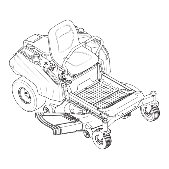
ZVT 4200
WARNING
READ AND FOLLOW ALL SAFETY RULES AND INSTRUCTIONS IN THIS MANUAL
BEFORE ATTEMPTING TO OPERATE THIS MACHINE.
FAILURE TO COMPLY WITH THESE INSTRUCTIONS MAY RESULT IN PERSONAL INJURY.
MASPORT PTY LIMITED, 1/40 ABBOTS RD, DANDENONG SOUTH, MELBOURNE, VICTORIA 3175
Printed In USA
Form No. 769-10034
(July 9, 2014)
Advertisement
Table of Contents

Related Manuals for Masport ZVT 4200


Summary of Contents for Masport ZVT 4200
- Page 1 READ AND FOLLOW ALL SAFETY RULES AND INSTRUCTIONS IN THIS MANUAL BEFORE ATTEMPTING TO OPERATE THIS MACHINE. FAILURE TO COMPLY WITH THESE INSTRUCTIONS MAY RESULT IN PERSONAL INJURY. MASPORT PTY LIMITED, 1/40 ABBOTS RD, DANDENONG SOUTH, MELBOURNE, VICTORIA 3175 Printed In USA Form No. 769-10034...
-
Page 2: Table Of Contents
Call a Customer Support Representative on 0800 627 767 (New Zealand) or 1300 366 225 (Australia) ◊ Write to Masport Limited • P.O. Box 14-349 • Panmure, Aukland • 1741 (New Zealand) ◊ Write to Masport Pty Limited • 1/40 Abbots Road • Dandenong South • Melbourne, Victoria • 3175 (Australia) -
Page 3: Safe Operation Practices
Important Safe Operation Practices WARNING! This symbol points out important safety instructions which, if not followed, could endanger the personal safety and/or property of yourself and others. Read and follow all instructions in this manual before attempting to operate this machine. Failure to comply with these instructions may result in personal injury. - Page 4 A missing or damaged discharge cover can cause blade Data indicates that operators, age 60 years and above, are contact or thrown object injuries. involved in a large percentage of riding mower-related injuries. These operators should evaluate their ability Stop the blade(s) when crossing gravel drives, walks, or to operate the riding mower safely enough to protect roads and while not cutting grass.
- Page 5 Children Never over fill fuel tank. Fill tank to no more than ½” below bottom of filler neck to allow space for fuel Tragic accidents can occur if the operator is not alert to the expansion. presence of children. Children are often attracted to the machine and the mowing activity.
- Page 6 Do not modify engine Grass catcher components and the discharge cover are subject to wear and damage which could expose moving To avoid serious injury or death, do not modify engine in any parts or allow objects to be thrown. For safety protection, way.
- Page 7 Safety Symbols This page depicts and describes safety symbols that may appear on this product. Read, understand, and follow all instructions on the machine before attempting to assemble and operate. Symbol Description READ THE OPERATOR’S MANUAL(S) Read, understand, and follow all instructions in the manual(s) before attempting to assemble and operate DANGER—...
- Page 8 Symbol Description WARNING— ACCIDENTAL STARTING Remove the ignition key before performing any adjustments, service or maintenance on the machine. WARNING— ACCIDENTAL STARTING Turn off the engine and disconnect the spark plug wire(s) before cleaning, checking, or performing any service or maintenance on the machine. WARNING—...
- Page 9 2 — i ection mportant peration racticeS...
-
Page 10: Assembly & Set-Up
Assembly & Set-Up Contents of Crate • One Lawn Tractor • One Oil Drain Hose (If Equipped) • One Deck Wash Hose Coupler • One RZT Tractor Operator’s Manual • One Engine Operator’s Manual • One Chute w/ Keys attached •... - Page 11 Rotate the seat into position and secure the seat into place Discharge with the previously removed shoulder bolts and lock nuts. Flange Lock Nuts Chute Be careful not to crimp or damage the wire harness while Deflector installing the seat. See Figure 3-5. Carriage Bolts Push Nuts...
- Page 12 Slide the flat washer onto the hex screw. From the outside, Position the red rubber boot over the positive battery insert the hex screw with washer through the control lever terminal to help protect it from corrosion. slot and the hole of the pivot bracket. See Figure 3-6. Using NOTE: If the battery is put into service after the date shown on top/ a 1⁄2”...
-
Page 13: Controls & Features
Controls & Features Deck Lift Handle Deck Height Index Throttle/Choke LH Drive RH Drive Control Control Lever Control Lever LCD Service Minder & Hour Meter Fuel Level Window Switch Ignition Switch Fuel Tank Holder Storage Tray RH Transmission LH Transmission Bypass Rod Bypass Rod Deck Height Index... - Page 14 Ignition Switch Fuel Tank Cap The ignition switch is located on the RH console The fuel tank cap is located near the middle of the LH console. to the rear of the PTO switch. The ignition switch Turn the fill cap approximately 1⁄4 turn and pull upward to has three positions as follows: remove.
- Page 15 LCD Service Minder & Hour Meter When the ignition key is rotated out of the STOP position but not into the START position, the LCD Service Minder and Hour Meter will briefly display the battery voltage, followed by the tractor’s accumulated hours.
-
Page 16: Operation
Operation General Safety • Unleaded gasoline is recommended because it leaves less combustion chamber deposits and reduces harmful exhaust • RECEIVE INSTRUCTION — Entirely read this operator’s emissions. Leaded gasoline is not recommended and must manual. Learn to operate this machine SAFELY. Do not risk not be used where exhaust emissions are regulated. - Page 17 Starting the Engine Allow the engine to run for a few minutes at mid-throttle before putting the engine under load. WARNING! This tractor is equipped with a safety Observe the hour meter/indicator panel. If the battery interlock system designed for the protection of the indicator light or oil pressure light come on, immediately operator.
- Page 18 Practice Operation (Initial Use) Move the throttle control lever forward to the full throttle position. Operating a zero-turn tractor is not like operating a conventional NOTE: Although the tractor’s engine is designed to run at type riding tractor. Although and because a zero turn tractor is full throttle, when performing a practice session the tractor more maneuverable, getting used to operating the control levers must be operated at less than full throttle.
- Page 19 Turning the Tractor While Driving Forward To execute a “pivot turn,” move the turn side drive control lever to the neutral position, while moving the other WARNING! When reversing the direction of travel, control lever forward. we recommend performing gradual ‘U’ turns where NOTE: Making a “pivot turn”...
- Page 20 Turning While Driving Rearward Executing a Zero Turn To turn the tractor while driving rearward, move the control WARNING! When executing a zero turn, the tractor levers as necessary so that one lever is forward of the other. The MUST BE STOPPED. Executing a zero turn while the tractor will turn in the direction of the forward control lever.
- Page 21 Stopping the Tractor Using the Mower Deck Move both drive control levers to the neutral position to WARNING! Make certain the area to be mowed is stop the motion of the tractor. free of debris, sticks, stones, wire or other objects that can be thrown by the rotating blades.
- Page 22 Checking the Safety Interlock Circuits Periodically check the safety interlock circuits to ensure they are working properly. If a safety circuit is not working as designed, contact you Cub Cadet dealer to have the tractor inspected. DO NOT operate the tractor if any safety circuit is not functioning properly.
-
Page 23: Maintenance & Adjustment
Maintenance & Adjustments Maintenance Schedule Before Every Every Every Every Prior Each use 10 Hours 25 Hours 50 Hours 100 Hours to Storing Check Engine Intake Screen/Cover Clean Battery Terminals Lube Front Wheels Clean Engine Cooling Fins Lube Front Deck Wheels NOTE: This Operator’s Manual covers several models. - Page 24 Tires The battery must be stored with a full charge. A discharged battery can freeze sooner than a charged battery. A fully Check the tire air pressure after every 50 hours of operation or charged battery will store longer in cold temperatures than hot. weekly.
- Page 25 Tractor Storage Removing The Tractor From Storage If your tractor is not going to be operated for an extended period Check the engine oil. of time (thirty days to approximately six months), the tractor should Fully charge the battery and inflate the tires to the be prepared for storage.
- Page 26 To adjust the drive control levers forward/rearward, proceed as Using a wrench, raise or lower the left side of the deck by follows: turning the adjustment gear. See Figure 6-4. If not already loose, loosen the hex screw and rotate the The deck is properly leveled when both blade tip measurements control lever either forward or rearward to the desired are equal.
- Page 27 Drive Control Lever Stop Adjustment Adjusting the Front Gauge Wheels WARNING!: Keep hands and feet away from the When the drive control levers are both fully extended forward discharge opening of the cutting deck. to the full-speed position and the tractor drifts left or right, the drive control lever stop adjustment can be adjusted to sync the wheel speeds.
- Page 28 Off-Season Storage Removing the Riding Mower from Storage Check the engine oil. Riding Mower Storage Fully charge the battery, lower riding mower off blocks, If your riding mower is not going to be operated for an extended and inflate the tires to the recommended pressure. period of time (thirty days to approximately six months), the riding Remove the spark plugs and wipe them off.
-
Page 29: Service
Service Battery Removal Charging the Battery WARNING! Test and, if necessary, recharge the battery after the tractor has Battery posts, terminals and related been stored for a period of time. accessories contain lead and lead compounds. Wash hands after handling. •... - Page 30 Releasing Belt Tension with the Idler Pulley Rolling the Belt off the PTO Pulley Using the deck lift handle, raise the deck to the position Using the deck lift handle, raise the deck to the position that that provides the most horizontal run of the belt between provides the most horizontal run of the belt between the deck the deck idler pulleys and the PTO pulley on the bottom of idler pulleys and the PTO pulley on the bottom of the engine.
- Page 31 Deck Installation Pull the cotter pin out of the front deck lift rod securing it to the deck. See Figure 7-6. Slide the deck lift rod out of the Install the deck on the tractor as follows: front hanger bracket. Place the deck lift handle in the highest mowing position See Figure 7-3.
- Page 32 Replacing the Belt Place the belt around the idler pulleys removed in step 3 with the “V” side facing in. Once in place, reinstall all the 42” Deck hardware and tighten the flange lock nut to secure the assembly. See Figure 7-8. Remove the deck from beneath the tractor, (refer to Deck Route the belt as shown in Figure 7-8 and then reinstall the Removal on page 28).
- Page 33 Remove the belt from the spindle pulleys. Remove the two idler pulleys by removing the hex screws and flange lock nuts that secure them to the deck and the Install the new belt around the spindle pulleys as shown idler arm. See Figure 7-12. Do not lose any of the hardware and reinstall the belt covers.
- Page 34 Mower Blade Care Changing the Transmission Drive Belt WARNING! Several components must be removed and special tools used in Before performing any maintenance, order to change the tractor’s transmission drive belt. See your place the PTO switch in the “OFF” position, engage the Cub Cadet dealer to have the transmission drive belt replaced.
-
Page 35: Troubleshooting
Troubleshooting Problem Cause Remedy Excessive vibration 1. Cutting blade loose or unbalanced. 1. Tighten blade and spindle. 2. Damaged or bent cutting blade. 2. Replace blade. Uneven cut 1. Deck not leveled properly. 1. Perform side-to-side deck adjustment. 2. Dull blade. 2. -
Page 36: Replacement Parts
0800 627 767 (New Zealand) or 1300 366 225 (Australia) Phone to order replacement parts or a complete Parts Manual (have your www.masport.com full model number and serial number ready). Parts Manual downloads are also available free of charge at... - Page 37 0800 627 767 (New Zealand) or 1300 366 225 (Australia) Phone to order replacement parts or a complete Parts Manual (have your www.masport.com full model number and serial number ready). Parts Manual downloads are also available free of charge at 9 — R...
-
Page 38: Warranty
3.6. For the “Full Parts and Labour” Level of Warranty Cover, Masport will repair or replace (at Masport’s sole option) any Product that suf- fers from a material defect in workmanship or materials. You will not be charged for any parts, materials or labour costs involved in the... - Page 39 Despite anything else in this warranty card, nothing in this warranty card will exclude, limit or modify any Consumer Protection War- ranty or any liability of Masport imposed by applicable law if to do so would be unlawful or make any part of this warranty card void or voidable.
- Page 40 Product was purchased, for example, an original receipt. 7.2. Masport or its agent will assess the claim and if accepted, will repair or replace the Product or Product Component in accordance with the normal practices of the relevant Masport service agent.
Need help?
Do you have a question about the ZVT 4200 and is the answer not in the manual?
Questions and answers