Advertisement
Advertisement
Table of Contents

Related Manuals for Masport Olympic 660


Summary of Contents for Masport Olympic 660
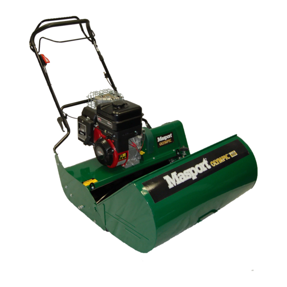
- Page 1 CYLINDER MOWER SERVICING MANUAL WWW.MASPORT.COM 032157.A.0...
- Page 3 Contents CONTROLS Engine Controls Throttle Control Adjustment Throttle Control Replacement OPC Control Adjustment Propulsion Controls Drive Clutch Drive Clutch Cable Adjustment MOWER ADJUSTMENTS Chains Front roller(s) Curing uneven cutting (weatherboarding) Cutting reel Grass deflector DISMANTLING THE MOWER Engine clutch Engine Clutch Spring Replacement Engine Clutch assembly Clutch Drum Assembly removal Roller clutch...
-
Page 4: Controls
The old control box can then be withdrawn from the top mount. Reverse this ALWAYS USE GENUINE MASPORT SPARE PARTS procedure to fit the new throttle control. Take care not to over-tighten the M6x60 screw that holds the control box to the top mount as this would make movement of the throttle lever very stiff. -
Page 5: Mower Adjustments
The plastic shoe should not be hard against the chain. Rotate the cutting cylinder several times in case there is a tight position of the chain. In the position where the chain is tightest, it should still be possible to move the chain with light hand pressure in and out a total of at least 5 millimetres at the mid point of the straight run between sprockets. -
Page 6: Grass Deflector
GRASS DEFLECTOR Step 3. Tip the mower backwards on its rear roller until the handle touches the ground. Place a weight on the handle to ensure the mower will stay safely in this position. This is the curved steel panel directly above the cutting reel. Its purpose is to direct the flow of air and grass clippings from the reel Step 4. -
Page 7: Engine Clutch Assembly
When removing the old springs, lever the spring end closest to the Step 4. The large drive clutch sprocket can now be pulled off to reveal shoe pivot post out of its slot first. When fitting the new springs, use the driven plate with its friction facing. -
Page 8: Rear Roller
REAR ROLLER Step 10. Remove the circlip and washer from each end of the shaft. The roller halves can then be withdrawn from the shaft to give access Dismantling procedure to the differential gears for servicing or lubrication. Step 1. To get access, it is necessary to carry out Steps 1 to 5 above for dismantling the drive clutch. -
Page 9: Dismantling The Cutting Unit
Later models. (From Serial No.7353010 – August 2010). These use Step 2. Back off the adjusting screws until they are no longer carrying a key to lock the bolted together sprocket assembly to the shaft. For any load. these, extract the retaining bolt in the centre of the shaft, and draw the sprocket off, using, if necessary, a wheel puller engaging behind Step 3. -
Page 10: Slow Down Kit
Slow Down Kit For customers who want to have a lower ground speed Masport has created a Slow Down Kit, part number 732181 Shaft cover Content of this kit Part No. Description Quantity Chain cover 032174 SPROCKET-26T,REEL 032186 CHAIN-ONLY 3/16XP 1/2, 42P R/M 032187 CHAIN-ONLY 0.23XP 3/8, 77P R/M... - Page 11 REEL DRIVE – REMOVAL Lock the reel so that it can’t be turned using a piece of timber, or similar. Undo the M8 set screw and remove the small sprocket from the sprocket assembly. Loosen the fixed adjuster so the chain can be removed. See below. Fixed adjuster.
- Page 12 REASSEMBLY – REEL DRIVE REASSEMBLY – ROLLER DRIVE 1. Refit the reel drive sprocket onto the shaft, check the key 1. Fit part #032188 SPROCKET & BOSS ASSY-R/ is in the slot on the shaft, and tap lightly into place. ROLLER, to the spindle.
Need help?
Do you have a question about the Olympic 660 and is the answer not in the manual?
Questions and answers