Table of Contents
Advertisement
Quick Links
IMPORTANT SAFETY INFORMATION: Always read this manual first before attempting to service this
fireplace. For your safety, always comply with all warnings and safety instructions contained in this
manual to prevent personal injury or property damage.
Dimplex North America Limited
1367 Industrial Road Cambridge ON Canada N3H 4W3
1-888-346-7539 www.dimplex.com
In keeping with our policy of continuous product development, we reserve the right to make changes without notice.
© 2016 Dimplex North America Limited
"Click" on the replacement part number to
view price and availability.
www.morelectricheating.com
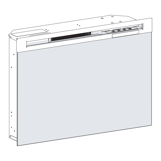
Service Manual
Model Number:
DFR2551L
DFR2551G
UL Part Number
6908922259
6908922559
REV
PCN
DATE
00
-
6-JAN-16
7400910100R00
Advertisement
Table of Contents

Summary of Contents for Dimplex DFR2551G
- Page 1 Dimplex North America Limited 6-JAN-16 1367 Industrial Road Cambridge ON Canada N3H 4W3 1-888-346-7539 www.dimplex.com In keeping with our policy of continuous product development, we reserve the right to make changes without notice. © 2016 Dimplex North America Limited 7400910100R00...
-
Page 2: Table Of Contents
NOTE: Procedures and techniques that are considered important enough to emphasize. CAUTION: Procedures and techniques which, if not carefully followed, will result in damage to the equipment. WARNING: Procedures and techniques which, if not carefully followed, will expose the user to the risk of fire, serious injury, or death. www.dimplex.com... -
Page 3: Operation
OPERATION heat) or the (high heat) icon and the intake temperature Figure 1 will continuously be displayed on the On Screen Display. ! NOTE: The heater may emit a slight, harmless odor when first used. This odor is a normal condition caused by initial heating of internal heater. -
Page 4: Maintenance
2. Correctly install one 3 Volt (CR2032 [longer life] or CR2025) battery in the battery holder. 3. Close the battery cover. Battery must be recycled or disposed of properly. Check with your Local Authority or Retailer for recyc- ling advice in your area Figure 2 www.dimplex.com... -
Page 5: Exploded Parts Diagram
EXPLODED PARTS DIAGRAM "Click" on the replacement part number to view price and availability. www.morelectricheating.com REPLACEMENT PARTS 1. Flicker Motor .....2000500100RP 12. -
Page 6: Wiring Diagram
WIRING DIAGRAM ELEMENT CUTOUT BLOWER MOTOR +T° FLICKER MOTOR 120V / 12V AC/DC ADAPTER AC / DC RELAY BOARD MEDIA BED RGB LED STRIP SWITCHBOARD LOGSET ASSEMBLY MEDIA BED LED ASSEMBLY LOGSET LED ASSEMBLY LED LIGHT ASSEMBLY THERMISTOR DISPLAY-CONTROL BOARD www.dimplex.com... -
Page 7: Switchboard Replacement
SWITCHBOARD REPLACEMENT RELAY BOARD REPLACEMENT Tools Required: Phillips Head Screwdriver Tools Required: Phillips Head Screwdriver Needle Nose Pliers Flat Head Screwdriver Needle Nose Pliers CAUTION: If unit was operating prior to servicing allow at least 10 minutes for lights, heating elements and top CAUTION: If unit was operating prior to servicing allow panel to cool off to avoid accidental burning of skin. -
Page 8: Ac/Dc Adapter Replacement
12. Properly orient and insert the new adapter and connect all of the wiring. NOTE: If any tie wraps were removed, replace and en- sure that none of the wires are pinched during reassembly. 13. Reassemble in the reverse order as above. www.dimplex.com... -
Page 9: Heater Assembly Replacement
HEATER ASSEMBLY REPLACEMENT the two on either side along the top edge and the one at the top of the glass retaining bracket on both sides. Tools Required: Phillips Head Screwdriver (Figure 3) Flat Head Screwdriver 5. Lay the Compact Fireplace on its back. CAUTION: If unit was operating prior to servicing allow 6. -
Page 10: Flame Led Light Assembly Replacement
2. Remove the front glass and set aside in a safe place. Assembly Thermistor 3. Remove the firebox from the back of the mantel by Colored Flame LED Flicker removing the retaining screws which secure the firebox Light Assembly Motor www.dimplex.com... -
Page 11: Partially Reflective Panel Replacement
THERMISTOR REPLACEMENT brackets to the mantel. 4. Remove the front glass and set aside in a safe place. Tools Required: Phillips Head Screwdriver 5. Pull the front edge of the plastic Ember Bed or plastic CAUTION: If unit was operating prior to servicing allow grate up and forward until the rear tab releases from at least 10 minutes for lights, heating elements and top the ledge located at the bottom of the Partially Reflect-... -
Page 12: Troubleshooting Guide
Replace the color flame LED light assembly Log 3001500100RP Glass 3001500200RP not working Flame Shudder Defective Flicker Motor Replace Flicker Motor 2000500100RP Light leaking around the log Log set not positioned properly Check log set for proper fit set (if applicable) www.dimplex.com... - Page 13 PROBLEM CAUSE SOLUTION Heater Heater is not turning off Improper operation Refer to Operation Section Defective switchboard Replace switchboard 3001520100RP Defective thermistor Replace thermistor 3001560100RP Defective relay board Replace the relay board 3001440100RP Defective display/control board Replace the display/control board Log 3001430100RP Glass 3001430300RP Heater is not turning on, but...


Need help?
Do you have a question about the DFR2551G and is the answer not in the manual?
Questions and answers