Table of Contents
Advertisement
Quick Links
Advertisement
Table of Contents

Related Manuals for Premio CT-XCL01 Series


Summary of Contents for Premio CT-XCL01 Series
- Page 1 USER’S MANUAL CT-XCL01 Series Mini-ITX Industrial Motherboard...
-
Page 2: Table Of Contents
CT-XCL01 l User’s Manual Table of Contents Prefaces …………………………………………………….……………………………………………. 04 Revision …………………………………………………………………………………………..……………….……….. 04 Disclaimer ………………………………………………………..…….…….………………………….……………….. 04 Copyright Notice …………………………………….…………………….…………………………………………… 04 Trademarks Acknowledgment …………..………………………………………………………....04 Environmental Protection Announcement …………………………….………………….……………….. 04 Safety Precautions ………………………………………….……………………………….…………….………….. 05 Technical Support and Assistance …………………………………….…………….…………….…………….06 Conventions Used in this Manual ………………………………………………………………….….………..06 Package Contents …………………………………………………………………………………………….…………... - Page 3 CT-XCL01 l User’s Manual 4.3.11 Network Stack Configuration ……………………………….……………..……... 51 4.3.12 Compatibility Support Module Configuration .……………….……..……... 52 4.3.13 NVMe Configuration …………………………………………………………….……... 53 4.3.14 USB Configuration ………………………….……………………………….…………... 54 Chipset …………...……….………………….…..….…..…………..…………………………..…..55 4.4.1 System Agent Configuration ………………….…………..……………..………….. 55 4.4.2 PCH-IO Configuration ………….…………………………………..…………………….. 59 Security …………...……….………………….…..….…..………………………..……..…………...
-
Page 4: Prefaces
2023/07/14 Disclaimer All specifications and information in this User’s Manual are believed to be accurate and up to date. Premio Inc. does not guarantee that the contents herein are complete, true, accurate or non-misleading. The information in this document is subject to change without notice and does not represent a commitment on the part of Premio Inc. -
Page 5: Safety Precautions
Preface CT-XCL01 l User’s Manual Safety Precautions Before installing and using the equipment, please read the following precautions: ⚫ Put this equipment on a reliable surface during installation. Dropping it or letting it fall could cause damage. ⚫ The power outlet shall be installed near the equipment and shall be easily accessible. ⚫... -
Page 6: Technical Support And Assistance
Preface CT-XCL01 l User’s Manual Technical Support and Assistance 1. Visit the Premio Inc website at www.premioinc.com where you can find the latest information about the product. 2. Contact your distributor, our technical support team or sales representative for technical support if you need additional assistance. -
Page 7: Package Contents
Preface CT-XCL01 l User’s Manual Package Contents Before installation, please ensure all the items listed in the following table are included in the package. Item Description CT-XCL01 Mini-ITX Industrial Motherboard I/O shield SATA Cable Ordering Information Model No. Product Description Mini-ITX Industrial Motherboard with LGA 1151 Socket supporting CT-XCL01 8th/9th Gen Intel®... -
Page 8: Chapter 1 Product Introductions
Chapter 1 Product Introductions... -
Page 9: Overview
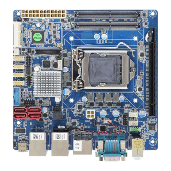
CT-XCL01 l User’s Manual Chapter 1: Product Introductions 1.1 Overview CT-XCL01 is a mini-ITX industrial motherboard with LGA1151 socket to support Intel 8th/9th Generation Core i7/i5/i3, and Pentium Processor. Two DDR4 SODIMM memory sockets enables a maximum of 32GB. The integrated Intel® UHD Graphics 610/630 with the processor supports three independent displays from the DVI, DisplayPort, HDMI, or LVDS onboard. -
Page 10: Hardware Specification
CT-XCL01 l User’s Manual Chapter 1: Product Introductions 1.2 Hardware Specification System Rear I/O • Processor: LGA 1151 socket supporting 8th/9th Gen • Display: 1x DVI-D, 1x DisplayPort, 1x HDMI • COM: 1x RS-232/422/485 Intel® Core™ i3/i5/i7 Desktop Processor • USB: 4x USB 3.2 Gen 1 - Intel®... -
Page 11: Block Diagram
CT-XCL01 l User’s Manual Chapter 1: Product Introductions 1.3 Block Diagram... -
Page 12: Board Dimensions
CT-XCL01 l User’s Manual Chapter 1: Product Introductions 1.4 Board Dimensions Unit: mm 170mm 170mm... -
Page 13: Chapter 2 Jumper And Connectors
Chapter 2 Jumper and Connectors... -
Page 14: Switch And Connector Locations
CT-XCL01 l User’s Manual Chapter 2: Jumper & Connectors 2.1 Switch & Connector Locations 2.1.1 Top View EATXPWR1 SODIMM_B1 SODIMM_A1 MINI_CARD1 MINI_CARD1_1 JCASE1 JLVDS1 COM2 JLPC1 LVU1 COM3 TPM-U1 COM4 PCIEX16_1 JDI01 COM5 USB56 USB78 SATA2 F_PANEL1 SPI1 SATA4 SATA3 CPU_FAN1 SATA1 SYS_FAN1... -
Page 15: Bottom View
CT-XCL01 l User’s Manual Chapter 2: Jumper & Connectors 2.1.2 Bottom View M2_1 SPK1 2.1.3 Back Panel View Audio 2x RJ45 LAN DisplayPort 1.2 USB Type-C DVI-D HDMI 4x USB 3.2 Gen 1... -
Page 16: Connector Definition
CT-XCL01 l User’s Manual Chapter 2: Jumper & Connectors 2.2 Connectors Definition List of Connectors Connectors Location Definition HDMI1_DP1 HDMI and DisplayPort Ports DVI-D1 DVI-D Connector COM1 Serial Port LAN1_USB12 LAN1 and USB3.0 Ports LAN2_USB34 LAN2 and USB3.0 Ports AUDIO1 Line-out and Microphone in PCIEX16_1 PCI-Express X16 Slot... - Page 17 CT-XCL01 l User’s Manual Chapter 2: Jumper & Connectors HDMI1_DP1: HDMI and DisplayPort Ports Definition Definition DP_DP0 HDMI_DP2 DP_DN0 HDMI_DN2 DP_DP1 HDMI_DP1 DP_DN1 HDMI_DN1 DP_DP2 HDMI_DP0 DP_DN2 HDMI_DN0 DP_DP3 HDMI_CKP DP_DN3 HDMI_CKN DP / HDMI Singnal Switch DP_AUXP HDMI_DDC_CLK HDMI_DDC_DATA DP_AUXN DP_Hot Plug HDMI_PWR...
- Page 18 CT-XCL01 l User’s Manual Chapter 2: Jumper & Connectors DVI-D1: DVI-D Connector Definition Definition DVI_TX2- DVI Hot Plug DVI_TX2+ DVI_TX0- DVI_TX0+ DVI_DDC_CLOCK DVI_DDC_DATA DVI_CLK+ DVI_TX1- DVI_CLK- DVI_TX1+ COM1: Serial Port Connector Type: 9-pin D-Sub Definition DCD1 RXD1 TXD1 DTR1 DSR1 RTS1 CTS1 KEY (No Pin)
- Page 19 CT-XCL01 l User’s Manual Chapter 2: Jumper & Connectors LAN1_USB12: LAN1 and USB3.0 Ports Connector Type: RJ45 port with LEDs and dual USB3.0 ports Definition Definition Definition LAN1_MDI0P USB2_D1- USB2_D2- LAN1_MDI0N USB2_D1+ USB2_D2+ LAN1_MDI1P LAN1_MDI2P USB3_RX1- USB3_RX2- LAN1_MDI2N USB3_RX1+ USB3_RX2+ LAN1_MDI1N LAN1_MDI3P USB3_TX1-...
- Page 20 CT-XCL01 l User’s Manual Chapter 2: Jumper & Connectors PCIEX16_1: PCI-Express X16 Socket Connector Type: PCI-Express X16 Slot Definition Definition Definition Definition PRSNT#1 +12v HSOn(6) +12v HSIp(6) +12v +12v HSIn(6) +12v HSOp(7) JTAG2 SMCLK HSOn(7) JTAG3 HSIp(7) SMDAT JTAG4 HSIn(7) PRSNT#2 JTAG5 +3.3v...
- Page 21 CT-XCL01 l User’s Manual Chapter 2: Jumper & Connectors JLVDS1: LVDS Connector Connector Type: 2x20-pin pitch1.25mm LVDS connector Definition Definition VDD_LVDS VDD_LVDS VDD_LVDS VDD_LVDS LVDS_A0- LVDS_B0- LVDS_A0+ LVDS_B0+ LVDS_A1- LVDS_B1- LVDS_A1+ LVDS_B1+ LVDS_A2- LVDS_B2- LVDS_A2+ LVDS_B2+ LVDS_A_CLK- LVDS_B_CLK- LVDS_A_CLK+ LVDS_B_CLK+ DDC_CLK DDC_DATA LVDS_A3-...
- Page 22 CT-XCL01 l User’s Manual Chapter 2: Jumper & Connectors USB78: Front Panel USB2.0 Header Pin Header Type: 2X5-pin header, 2.54mm pitch Definition Definition +5 VDC +5 VDC *The +5 VDC power on the USB headers is fused SATA1, SATA2, SATA3, SATA4: SATA Connector SATA1 SATA2 SATA3...
- Page 23 CT-XCL01 l User’s Manual Chapter 2: Jumper & Connectors Definition Definition MIC2-IN_L PRESENCE# MIC2-IN_R (Dongle present) MIC2-IN LINE2-IN_R SENSE_RETURN Jack Detect LINE2-IN LINE2-IN_L SENSE_RETURN CPU_FAN1, SYS_FAN1: FAN Connector Definition +12V FAN Tachometer FAN PWM F_PANEL1: Front Panel Header Pin Header Type: 2X5-pin header, 2.54mm pitch Definition Definition RESET...
- Page 24 CT-XCL01 l User’s Manual Chapter 2: Jumper & Connectors EATXPWR1: Main Power Supply Connector (24pin) Definition Definition +3.3V +3.3V +3.3V -12V PS-ON PWRGD +5VSB +12V +12V +3.3V ATX12V1: Processor Power Supply Connector (4pin) Definition +12V / 16~24 VDC +12V / 16~24 VDC JLPC1: Debug Header Pin Header Type: 2X5-pin header, 2.0mm pitch Definition...
- Page 25 CT-XCL01 l User’s Manual Chapter 2: Jumper & Connectors SPI1: SPI Header Pin Header Type: 2X4-pin header, 2.0mm pitch Definition Definition +3.3V SPI_CS# SPI_CLK SPI_MISO SPI_MOSI HOLD# JDIO1: GPIO Connector (8 bits) Connector Type: Connector Type: 2X5-pin Wafer, 2.0mm pitch Definition Definition GPIO0...
- Page 26 CT-XCL01 l User’s Manual Chapter 2: Jumper & Connectors MINI_CARD1_1: Mini PCI-Express Definition Definition 27 GND Reserved 3.3V 28 1.5V 29 GND Reserved 30 SMB_CLK Reserved 31 A- 32 SMB_DATA 1.5V 33 A+ Reserved 34 GND Reserved 35 GND 10 Reserved 36 Reserved 11 Reserved 37 Reserved...
- Page 27 CT-XCL01 l User’s Manual Chapter 2: Jumper & Connectors NGFF1: M.2 Socket Definition Definition +3.3V +3.3V +3.3V +3.3V +3.3V +3.3V SATA_DEVSLP SATA_RXP5 SATA_RXN5 SATA_TXN5 SATA_TXP5 RESET M2_CLKREQ# M2_CLKN WAKE# M2_CLKP PCH_SUSCLK +3.3V SATA/PCIE_Detection +3.3V +3.3V...
- Page 28 CT-XCL01 l User’s Manual Chapter 2: Jumper & Connectors USB56: USB3.0 Connector Connector Type: 2X10 20-pin box header, 2.0mm pitch Definition Definition +5 VDC USB_P6 USB3_RX_N7 USB_N6 USB3_RX_P7 USB3_TX_P8 USB3_TX_N7 USB3_TX_N8 USB3_TX_P7 USB3_RX_P8 USB_N5 USB3_RX_N8 USB_P5 +5 VDC *The +5 VDC power on the USB headers is fused...
-
Page 29: Jumpers Definition
CT-XCL01 l User’s Manual Chapter 2: Jumper & Connectors 2.3 Jumpers Definition When setting the jumpers, ensure that the jumper caps are placed on the correct pins. When the jumper cap is placed on both pins, the jumper is short. If you remove the jumper cap, or place the jumper cap on just one pin, the jumper is open. - Page 30 CT-XCL01 l User’s Manual Chapter 2: Jumper & Connectors JLVDS2: Backlight Power Select Header Pin Header Type: 2X3-pin header, 2.0mm pitch Definition 1-3 (Short) 3-5 (Short) +3.3V 3-4 (Short) +12V JPSON1: AT / ATX Mode Select Header Pin Header Type: 1X3-pin header, 2.54mm pitch Definition 1-2 (Short) ATX Mode...
-
Page 31: Chapter 3 Features & Interface
Chapter 3 Features & Interface... -
Page 32: General Purpose Input & Output (Gpio)
CT-XCL01 l User’s Manual Chapter 3: Features & Interface 3.1 General Purpose Input Output (GPIO) GPI and GPO pins may be implemented as GPIO. GPI and GPO pins may be implemented as SDIO. Signal Description General purpose output pins. Upon a hardware reset, these GPO[0:3] outputs should be low. -
Page 33: Watchdog Timer
CT-XCL01 l User’s Manual Chapter 3: Features & Interface Registers Description GPIO I/O Select I/O Register: 0xEC Bit 7 Bit 6 Bit 5 Bit 4 Bit 3 Bit 2 Bit 1 Bit 0 GPO3 GPO2 GPO1 GPO0 GPI3 GPI2 GPI1 GPI0 Note. -
Page 34: Psuedo Code
CT-XCL01 l User’s Manual Chapter 3: Features & Interface 3.2.2 Psuedo Code ◼ Enter_Config Step1: outportb(0x2e, 0x87); Step2: outportb(0x2e, 0x87); ◼ Select Logical Device: 8 Step1: outportb(0x2e, 0x07); Step2: outportb(0x2e, 0x07); ◼ Set WDT Time Unit (Second Unit) Step1: outportb(0x2e, 0xf0); Step2: buf2 = inportb(0x2f) &... - Page 35 CT-XCL01 l User’s Manual Chapter 3: Features & Interface Watchdog Timer: Logical Device: 8 CR F0h. Watchdog Timer I (WDT1) and KBC P20 Control Mode Register Location: Address F0h Attribute: Read/Write Power Well: VCC Reset by: LRESET# or PWROK Default: 00h Size: 8 bits READ / WRITE DESCRIPTION...
-
Page 36: Chapter 4 Bios Setup
Chapter 4 BIOS Setup... -
Page 37: Bios Introduction
CT-XCL01 l User’s Manual Chapter 4: BIOS Setup 4.1 BIOS Introduction The system BIOS software is stored on EEPROM. The BIOS provides an interface to modify the configuration. When the battery is removed, all the parameters will be reset. BIOS Setup Power on the embedded system and by pressing <Del>... -
Page 38: Main Setup
CT-XCL01 l User’s Manual Chapter 4: BIOS Setup 4.2 Main Setup Press <Del> to enter BIOS CMOS Setup Utility. The Main setup screen is showed as following when the setup utility is entered. System Date/Time is set up in the Main Menu. 4.2.1 System Date Set the system date. -
Page 39: Advanced Setup
CT-XCL01 l User’s Manual Chapter 4: BIOS Setup 4.3 Advanced Setup Select the Advanced tab from the setup screen to enter the Advanced BIOS Setup screen. You can select any of the items in the left frame of the screen, such as Chipset configuration, to go to the sub menu for that item. -
Page 40: Trusted Computing
CT-XCL01 l User’s Manual Chapter 4: BIOS Setup 4.3.1 Trusted Computing ■ Security Device Support This item allows you to enable or disable BIOS support for security device. -
Page 41: Acpi Settings
CT-XCL01 l User’s Manual Chapter 4: BIOS Setup 4.3.2 ACPI Settings ■ Enable Hibernation Enable or Disable system ability to Hibernation. Configuration options: [Enable] [Disable] ■ ACPI Sleep State Select the highest ACPI sleep state the system will enter the SUSPEND button is press. Configuration options: [Suspend Disable] [S3 only(suspend to RAM )] ■... -
Page 42: Amt Configuration
CT-XCL01 l User’s Manual Chapter 4: BIOS Setup 4.3.3 AMT Configuration ■ Intel AMT Enable or Disable Intel AMT BIOS extension Configuration options: [Disabled] [Enabled] ■ Un-configure ME Un-configure ME with Password Configuration options: [Disabled] [Enabled] 4.3.4 PCH FW Configuration... -
Page 43: Super Io Configuration
CT-XCL01 l User’s Manual Chapter 4: BIOS Setup 4.3.5 Super IO Configuration This setting allows you to select options for the NCT6106D Super IO Configuration, and change the value of the selected option. ■ Serial Port 1 Configuration ❑ Serial Port This item allows you to enable or disable serial port. - Page 44 CT-XCL01 l User’s Manual Chapter 4: BIOS Setup ■ Serial Port 2 Configuration ❑ Serial Port This item allows you to enable or disable serial port. ❑ Change Settings This item allows you to change the address & IRQ settings of the specified serial port. ❑...
- Page 45 CT-XCL01 l User’s Manual Chapter 4: BIOS Setup ■ Serial Port 4 Configuration ❑ Serial Port This item allows you to enable or disable serial port. ❑ Change Settings This item allows you to change the address & IRQ settings of the specified serial port. ❑...
-
Page 46: Hardware Monitor
CT-XCL01 l User’s Manual Chapter 4: BIOS Setup ■ Watch Dog Function This setting allows you to setup the system watch-dog timer, a hardware timer that generates a reset when the software that it monitors does not respond as expected each time the watch dog polls it. ❑... -
Page 47: Serial Port Console Redirection
CT-XCL01 l User’s Manual Chapter 4: BIOS Setup 4.3.7 Serial Port Console Redirection ■ Console Redirection These items allows you to enable or disable COM1~COM5 console redirection. 4.3.8 CPU Configuration... - Page 48 CT-XCL01 l User’s Manual Chapter 4: BIOS Setup ■ Hyper-Threading [Enabled] Enabled or Disabled the hyper threading of Intel CPU Configuration options: [Disabled][Enabled] This depends on CPU sku. ■ Active Processor Core [All] Number of Cores to enable in each processor package Configuration options: [all] [1][2][3][4] This depends on CPU sku.
-
Page 49: Intel Txt Information
CT-XCL01 l User’s Manual Chapter 4: BIOS Setup 4.3.9 Intel TXT Information Display Intel TXT information... -
Page 50: Sata Configuration
CT-XCL01 l User’s Manual Chapter 4: BIOS Setup 4.3.10 SATA Configuration ■ SATA Controller [Enabled] Enable or Disable SATA device Configuration options: [Enabled][Disabled] ■ SATA Mode Selection [AHCI] Determines how SATA controller operate Configuration options: [AHCI][RAID] ■ Serial – ATA Port 1 This item allows you to enable or disable Serial-ATA Port 1. -
Page 51: Network Stack Configuration
CT-XCL01 l User’s Manual Chapter 4: BIOS Setup 4.3.11 Network Stack Configuration ■ Network Stack [Disabled] Enabled or disabled UEFI Network Stack Configuration options: [Disabled] [Enabled]... -
Page 52: Compatibility Support Module Configuration
CT-XCL01 l User’s Manual Chapter 4: BIOS Setup 4.3.12 Compatibility Support Module Configuration ■ CSM Support Enabled or disabled CSM Support Configuration options: [Disabled] [Enabled] ■ Boot option filter This option controls Legacy/UEFI ROMs Priority Configuration options: [UEFI and Legacy] [Legacy Only][UEFI Only] ■... -
Page 53: Nvme Configuration
CT-XCL01 l User’s Manual Chapter 4: BIOS Setup 4.3.13 NVMe Configuration... -
Page 54: Usb Configuration
CT-XCL01 l User’s Manual Chapter 4: BIOS Setup 4.3.14 USB Configuration ■ Legacy USB Support [Enabled] Enabled Legacy USB Support. Auto Option disables legacy support if no USB devices are connected. Disabled option will keep USB devices available only for EFI application. Configuration options: [Disabled] [Enabled][Auto] ■... -
Page 55: Chipset
CT-XCL01 l User’s Manual Chapter 4: BIOS Setup 4.4 Chipset 4.4.1 System Agent Configuration This section provides configure options for on-graphic, PEG port, and installed memory. - Page 56 CT-XCL01 l User’s Manual Chapter 4: BIOS Setup ■ Graphic Configuration This section provides onboard graphics-related configuration options. ❑ Primary Display Select which of IGFX/PEG/PCI graphic device should be primary display or select SG for switchable GFx. Configuration options: [Auto] [IGFX][PEG][PCIE] ❑...
- Page 57 CT-XCL01 l User’s Manual Chapter 4: BIOS Setup ■ PEG Port Configuration This section provides PEG Port configuration options. ❑ Enable root Port [Auto] Enable or Disable the root port Configuration options: [Disabled][Enabled][Auto] ❑ Max Link Speed [Auto] Configure PEG 0:1:0 Max Speed Configuration options: [Auto][Gen1][Gen2][Gen3] ❑...
- Page 58 CT-XCL01 l User’s Manual Chapter 4: BIOS Setup ■ Memory Configuration This section provides installed memory information.
-
Page 59: Pch-Io Configuration
CT-XCL01 l User’s Manual Chapter 4: BIOS Setup 4.4.2 PCH-IO Configuration ■ Lan1 Controller [Enabled] Enable or Disable onboard Lan1 Configuration options: [Disabled][Enabled] ■ Wake on lan [Auto] Enable or Disable integrated LAN to wake the system Configuration options: [Disabled][Enabled] ■... - Page 60 CT-XCL01 l User’s Manual Chapter 4: BIOS Setup ■ PCI Express Configuration ❑ PCI Express Root Port 9 [Enabled] Control the PCI Express Port Configuration options: [Disabled][Enabled] ❑ ASPM Support [Disabled] Set the ASPM level: Force L0s- Force all links to L0s State; Auto- BIOS auto configure; Disabled- Disables ASPM Configuration options: [Disabled][L0s][L1][L0sL2][Auto] ❑...
- Page 61 CT-XCL01 l User’s Manual Chapter 4: BIOS Setup ■ USB Configuration ❑ USB Precondition[Disabled] Precondition work on USB host controller and root ports for faster enumeration Configuration options: [Disabled] [Enabled] ❑ XHCI Disabled Compliance Mode [False] Options to disable compliance mode. Configuration options: [False][true] ❑...
-
Page 62: Security
CT-XCL01 l User’s Manual Chapter 4: BIOS Setup ■ HD Audio Configuration Control Detection of the HD-Audio device. Configuration options: [Disabled] [Enabled][Auto] 4.5 Security Security menu allow you to change administrator password and user password settings. 4.5.1 Administrator Password This item allows you to set Administrator Password. 4.5.2 User Password This item allows you to set User Password. -
Page 63: Boot
CT-XCL01 l User’s Manual Chapter 4: BIOS Setup 4.6 Boot This menu allows you to setup the system boot options. 4.6.1 Setup Prompt Timeout Number of seconds to wait for setup activation key. 65535(0xFFFF) means indefinite waiting. 4.6.2 Bootup NumLock State This item selects the keyboard NumLock state. -
Page 64: Save & Exit
CT-XCL01 l User’s Manual Chapter 4: BIOS Setup 4.7 Save & Exit This setting allows you to configure the boot settings. 4.7.1 Save Changes and Exit This item allows you exit BIOS Setup after saving the changes. 4.7.2 Discard Changes and Exit Select this option to quit Setup without making any permanent changes to the system configuration. - Page 65 Premio Inc. All Rights Reserved www.premioinc.com...
Need help?
Do you have a question about the CT-XCL01 Series and is the answer not in the manual?
Questions and answers