
Related Manuals for Premio CT-NR101


Summary of Contents for Premio CT-NR101
- Page 1 USER’S MANUAL CT-NR101 1.8“ SBC Industrial Motherboard with AMD Ryzen™ Embedded R1000 Series Processor...
-
Page 2: Table Of Contents
CT-NR101 l User’s Manual Table of Contents Prefaces …………………………………………………….……………………………………………. 04 Revision …………………………………………………………………………………………..……………….……….. 04 Disclaimer ………………………………………………………..…….…….………………………….……………….. 04 Copyright Notice …………………………………….…………………….…………………………………………… 04 Trademarks Acknowledgment …………..………………………………………………………....04 Environmental Protection Announcement …………………………….………………….…………..….. 04 Safety Precautions ………………………………………….……………………………….…………….………..05 Technical Support and Assistance …………………………………….…………….…………….………….. 06 Conventions Used in this Manual ………………………………………………………………….….………. 06 Chapter 1 Product Introductions ………………………………………………………..…... - Page 3 CT-NR101 l User’s Manual Chipset ………….………………………………............37 4.4.1 SB USB Configuration ………………..……………………………..……………… 37 4.4.2 North Bridge Configuration ...……………………………..………………..… 38 Security …….……………………..……………............39 Boot ……………..………………………………............42 Save and Exit …………………………………............43 Appendix WDT & GPIO .…………………………..………………..……………..…..…. WDT Sample Code ………………………..………............ 45...
-
Page 4: Prefaces
2022/07/14 Disclaimer All specifications and information in this User’s Manual are believed to be accurate and up to date. Premio Inc. does not guarantee that the contents herein are complete, true, accurate or non-misleading. The information in this document is subject to change without notice and does not represent a commitment on the part of Premio Inc. -
Page 5: Safety Precautions
Preface CT-NR101 l User’s Manual Safety Precautions Before installing and using the equipment, please read the following precautions: Put this equipment on a reliable surface during installation. Dropping it or letting it fall could cause damage. The power outlet shall be installed near the equipment and shall be easily accessible. -
Page 6: Technical Support And Assistance
Preface CT-NR101 l User’s Manual Technical Support and Assistance 1. Visit the Premio Inc website at premioinc.com where you can find the latest information about the product. 2. Contact your distributor, our technical support team or sales representative for technical support if you need additional assistance. -
Page 7: Chapter 1 Product Introductions
Chapter 1 Product Introductions... -
Page 8: Product Description
CT-NR101 l User’s Manual Chapter 1: Product Introductions 1.1 Product Description The CT-NR101 is a single board computer in 1.8“ SBC Industrial Motherboard with AMD Ryzen™ Embedded R1000 Series Processor • Femto-ITX form factor 1.8" SBC for space-limited applications • AMD Ryzen™ Embedded R1000 Series •... -
Page 9: Specifications
CT-NR101 l User’s Manual Chapter 1: Product Introductions 1.2 Specifications System Operating System Processor Windows Windows 10 Support AMD Ryzen™ Embedded R1000 Series Linux Linux Kernel 5.x (Fedora 30 or above / • AMD Ryzen™ Embedded R1606G with Radeon™ Vega Ubuntu 19.04 or above) -
Page 10: Available Models
CT-NR101 l User’s Manual Chapter 1: Product Introductions 1.3 Available Models Ordering Information DESCRIPTION CT-NR101-R1606G 1.8" SBC with AMD Ryzen™ Embedded R1606G, 2x Micro HDMI, 1x USB 3.2 Gen 1 Type-C Packing List • 1x CT-NR10x Main Board • 1x Heat Sink and screws •... -
Page 11: Chapter 2 Mechanical Specifications
Chapter 2 Mechanical Specifications... -
Page 12: Switch And Connector Locations
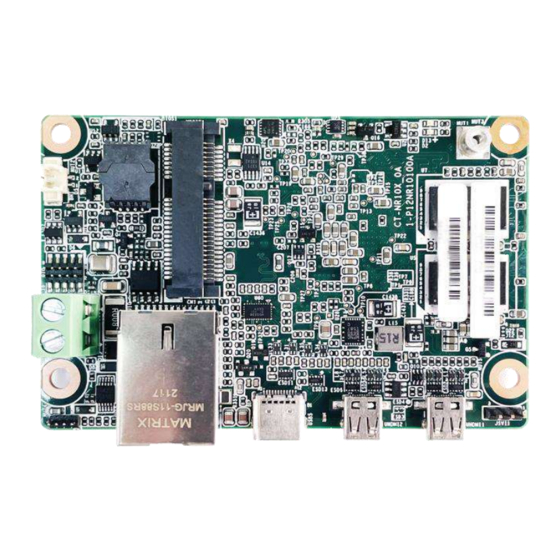
CT-NR101 l User’s Manual Chapter 2: Mechanical Specifications 2.1 Switch and Connector Locations 2.1.1 Top View DCIN1 USB2 USB5 UHDMI2 UHDMI1 2.1.2 Bottom view 2.1.3 Rear I/O... -
Page 13: Connector / Switch Definition
CT-NR101 l User’s Manual Chapter 2: Mechanical Specifications 2.2 Connector / Switch Definition Connector Location Definition DCIN1 DC_IN Digital-I/O USB2 USB 2.0 header Front Panel SM BUS LAN RJ45 USB5 USB header UHDMI2 / UHDMI1 HDMI signal connector... -
Page 14: I/O Interface Descriptions
CT-NR101 l User’s Manual Chapter 2: Mechanical Specifications 2.3 I/O Interface Descriptions 2.3.1 DC_IN DCIN1 Signal +12V 2.3.2 Digital-I/O Signal Signal... -
Page 15: Usb2.0
CT-NR101 l User’s Manual Chapter 2: Mechanical Specifications 2.3 I/O Interface Descriptions 2.3.3 USB2.0 USB2 Signal Signal USB2.0_DP USB2.0_DM 2.3.4 Front panel Signal Signal SYSRST_IN# SYS_LED+ STBY_LED+ PB_IN#... -
Page 16: Sm Bus
CT-NR101 l User’s Manual Chapter 2: Mechanical Specifications 2.3 I/O Interface Descriptions 2.3.5 SM BUS Signal Signal SDATA1_SMB SCLK1_SMB 3VSB 2.3.6 LAN RJ45 Signal Signal BI_DA+ BI_DC- BI_DA- BI_DB- BI_DB+ BI_DD+ BI_DC+ BI_DD-... -
Page 17: Usb Type C
CT-NR101 l User’s Manual Chapter 2: Mechanical Specifications 2.3 I/O Interface Descriptions 2.3.7 USB Type C USB5 Signal Signal TX1+ RX1+ TX1- RX1- VBUS VBUS SBU2 SBU1 VBUS VBUS RX2- TX2- RX2+ TX2+... -
Page 18: Micro Hdmi_Type-D (Uhdmi2)
CT-NR101 l User’s Manual Chapter 2: Mechanical Specifications 2.3 I/O Interface Descriptions 2.3.8 MICRO HDMI_TYPE-D UHDMI2 Signal Signal Hot Plug Detect TMDS DATA2+ TMDS DATA2- TMDS DATA1+ TMDS DATA1- TMDS DATA0+ TMDS DATA0- TMDS CLOCK+ TMDS CLOCK- DDC_SCL DDC_SDA HDMI_5V... -
Page 19: Micro Hdmi_Type-D (Uhdmi1)
CT-NR101 l User’s Manual Chapter 2: Mechanical Specifications 2.3 I/O Interface Descriptions 2.3.9 MICRO HDMI_TYPE-D UHDMI1 Signal Signal Hot Plug Detect TMDS DATA2+ TMDS DATA2- TMDS DATA1+ TMDS DATA1- TMDS DATA0+ TMDS DATA0- TMDS CLOCK+ TMDS CLOCK- DDC_SCL DDC_SDA HDMI_5V... -
Page 20: Chapter 3 System Setup
Chapter 3 System Setup... -
Page 21: Heat Sink Installation (Standard)
CT-NR101 l User’s Manual Chapter 3: System Setup 3.1 Heat Sink Installation (Standard) Heat sink x1 Board x1 Screw x4 Bolt x4 Top view Bottom view... - Page 22 CT-NR101 l User’s Manual Chapter 3: System Setup Heat Sink Installation (Standard) Fasten the four screws on top and below to lock the heat sink.
-
Page 23: Heat Sink Installation (Customized)
CT-NR101 l User’s Manual Chapter 3: System Setup 3.2 Heat Sink Installation (Customized) Heat sink x1 Board x1 Screw x4 Top view Bottom view... - Page 24 CT-NR101 l User’s Manual Chapter 3: System Setup Heat Sink Installation (Customized) Fasten the four screws below to lock the heat sink.
-
Page 25: Chapter 4 System Bios
Chapter 4 System BIOS... -
Page 26: Bios Introduction
CT-NR101 l User’s Manual Chapter 4: BIOS Setup 4.1 BIOS Introduction The BIOS provides an interface to modify the configuration. When the battery is removed, all the parameters will be reset. BIOS Setup Power on the embedded system and by pressing <Del> immediately allows you to enter the setup screens. -
Page 27: Main Setup
CT-NR101 l User’s Manual Chapter 4: BIOS Setup 4.2 Main Setup Press <Del> to enter BIOS CMOS Setup Utility. The Main setup screen is showed as following when the setup utility is entered. System Date/Time is set up in the Main Menu. -
Page 28: Advanced Setup
CT-NR101 l User’s Manual Chapter 4: BIOS Setup 4.3 Advanced Setup... -
Page 29: Trusted Computing
CT-NR101 l User’s Manual Chapter 4: BIOS Setup 4.3.1 Trusted Computing Item Options Description Security Device Support Enabled, Enable/Disable BIOS support for security Disabled[Default] , device. O.S. will not show Security Device.TCG EFI protocol and INT1A interface will not be available. -
Page 30: Acpi Settings
CT-NR101 l User’s Manual Chapter 4: BIOS Setup 4.3.2 ACPI Settings Item Options Description Enable Hibernation Disabled , Enables or Disables System ability to Enabled[Default], Hibernate (OS/S4 Sleep State). This option may not be effective with some operating systems. ACPI Sleep State... -
Page 31: Hardware Monitor
CT-NR101 l User’s Manual Chapter 4: BIOS Setup 4.3.3 Hardware Monitor These items display the current status of all monitored hardware devices/ components such as voltages and temperatures. Item Options Description Smart Fan Function Disabled[Default], Enabled or Disable Smart Fan... -
Page 32: Cpu Configuration
CT-NR101 l User’s Manual Chapter 4: BIOS Setup 4.3.4 CPU Configuration Item Options Description PSS Support Disabled, Enable/disable the generation of ACPI _PPC, Enabled[Default] _PSS, and _PCT objects. NX Mode Disabled, Enable/disable No-execute page protection Enabled[Default] Function SVM Mode Disabled,... -
Page 33: Usb Configuration
CT-NR101 l User’s Manual Chapter 4: BIOS Setup 4.3.5 USB Configuration Item Options Description Legacy USB Enabled[Default] Enables Legacy USB support. AUTO Support Disabled option disables legacy support if no USB Auto devices are connected. DISABLE option will keep USB devices available only for EFI applications. -
Page 34: Network Stack Configuration
CT-NR101 l User’s Manual Chapter 4: BIOS Setup 4.3.6 Network Stack Configuration Item Options Description Network Stack Disabled[Default] , Enable/Disable UEFI Network Stack. Enabled IPv4 PXE Support Disabled[Default] , Enable/Disable IPv4 PXE boot support. If Enabled disabled, IPv4 PXE boot support will not be available. -
Page 35: Csm Configuration
CT-NR101 l User’s Manual Chapter 4: BIOS Setup 4.3.7 CSM Configuration Item Options Description CSM Support Disabled[Default] , This item allows users to enable or disable for Enabled “CSM Support”. GateA20 Active Upon Request[Default] , This item allows users to set Upon Request or Always Always for "GateA20 Active“. -
Page 36: Amd Cbs
CT-NR101 l User’s Manual Chapter 4: BIOS Setup 4.3.8 AMD CBS Item Options Description AC Loss Control Power Off, Specify what state to go to when power Power On[Default] , is re-applied after a power failure (G3 Last State state). -
Page 37: Chipset
CT-NR101 l User’s Manual Chapter 4: BIOS Setup 4.4 Chipset This section allows you to configure and improve your system and allows you to set up some system features according to your preference. 4.4.1 SB USB Configuration Item Options Description... -
Page 38: North Bridge Configuration
CT-NR101 l User’s Manual Chapter 4: BIOS Setup 4.4.2 North Bridge Configuration... -
Page 39: Security
CT-NR101 l User’s Manual Chapter 4: BIOS Setup 4.5 Security Security menu allow users to change administrator password and user password settings. ■ Administrator Password This item allows you to set Administrator Password. ■ User Password This item allows you to set User Password. - Page 40 CT-NR101 l User’s Manual Chapter 4: BIOS Setup ■ Security Boot Item Options Description Secure Boot Disabled [Default] , Secure Boot feature is Active if Secure Enabled Boot is Enabled,Platform Key(PK) is enrolled and the System is in User mode.
- Page 41 CT-NR101 l User’s Manual Chapter 4: BIOS Setup ■ Key Management Item Options Description Factory Key Disabled [Default] , Install factory default Secure Boot keys Provision Enabled after the platform reset and while the System is in Setup mode...
-
Page 42: Boot
CT-NR101 l User’s Manual Chapter 4: BIOS Setup 4.6 Boot This menu allows you to setup the system boot options. Item Options Description Setup Prompt 1[Default] Number of seconds to wait for setup Timeout activation key. 65535(0xFFFF) means indefinite waiting. -
Page 43: Save And Exit
CT-NR101 l User’s Manual Chapter 4: BIOS Setup 4.7 Save & Exit This setting allows users to configure the boot settings. ■ Save Changes and Reset This item allows user to reset the system after saving the changes. This item allows user to reset the system after saving the changes. -
Page 44: Appendix Wdt & Gpio
Appendix WDT & GPIO This appendix provides the sample codes of WDT (Watch Dog Timer) and GPIO (General Purpose Input/ Output). -
Page 45: Wdt Sample Code
Appendix – WDT & GPIO CT-NR101 l User’s Manual WDT Sample Code Psuedo Code UINT8 WDT_TimeOut_Sec=2; //Second value //Set Second Number *(volatile UINT32 *)0xFEB00000= 0x03; //Initialization WatchdogControl IoWrite8(0x80,0xFF); //Delay time *(volatile UINT32 *)0xFEB00004= WDT_TimeOut_Sec; //Set watch dog time value(Bit15~Bit0) IoWrite8(0x80,0xFF);... -
Page 46: Gpio Sample Code
CT-NR101 l User’s Manual Appendix – WDT & GPIO GPIO Sample Code GPIO Setting PIN# GPIO# Default Configuration +GND DIO Input1 OUT1 DIO Output1 DIO Input2 Psuedo Code UINT32 GPIO0_Value; OUT2 DIO Output2 UINT32 GPIO1_Value; UINT32 GPIO2_Value; DIO Input3 UINT32 GPIO3_Value;... - Page 47 © 2022 Premio Inc. All Rights Reserved www.premioinc.com...
Need help?
Do you have a question about the CT-NR101 and is the answer not in the manual?
Questions and answers