
Related Manuals for Premio CT-DR101


Summary of Contents for Premio CT-DR101
- Page 1 USER’S MANUAL CT-DR101 3.5“ SBC Industrial Motherboard with AMD Ryzen™ Embedded R1000/V1000 Series Processor...
-
Page 2: Table Of Contents
CT-DR101 l User’s Manual Table of Contents Prefaces …………………………………………………….……………………………………………. 04 Revision …………………………………………………………………………………………..……………….……….. 04 Disclaimer ………………………………………………………..…….…….………………………….……………….. 04 Copyright Notice …………………………………….…………………….…………………………………………… 04 Trademarks Acknowledgment …………..………………………………………………………....04 Environmental Protection Announcement …………………………….………………….…………..….. 04 Safety Precautions ………………………………………….……………………………….…………….………..05 Technical Support and Assistance …………………………………….…………….…………….………….. 06 Conventions Used in this Manual ………………………………………………………………….….………. 06 Chapter 1 Product Introductions ………………………………………………………..…... - Page 3 CT-DR101 l User’s Manual Chapter 3 System Setup …………………..………………..……………..…………….…. 40 Heat Sink Installation .….…………………………………..……...…….……..……..…..41 Chapter 4 System BIOS ….…………………………..………………..……………..…..…. 43 BIOS Introduction ………….….…………………………………..……...…….…..……..…..44 Main Setup ………….….…………………………………..……...…….……………..……..…..45 Advanced Setup ………….….…………………………………..……...…………..……..…..46 4.3.1 Trusted Computing …………….…………………………………………..…………… 47 4.3.2 ACPI Settings ………..…….………………..…………..…………………………..……… 48 4.3.3 IDE Configuration ...………………………………………………..…..………………...
-
Page 4: Prefaces
2022/07/14 Disclaimer All specifications and information in this User’s Manual are believed to be accurate and up to date. Premio Inc. does not guarantee that the contents herein are complete, true, accurate or non-misleading. The information in this document is subject to change without notice and does not represent a commitment on the part of Premio Inc. -
Page 5: Safety Precautions
Preface CT-DR101 l User’s Manual Safety Precautions Before installing and using the equipment, please read the following precautions: Put this equipment on a reliable surface during installation. Dropping it or letting it fall could cause damage. The power outlet shall be installed near the equipment and shall be easily accessible. -
Page 6: Technical Support And Assistance
Preface CT-DR101 l User’s Manual Technical Support and Assistance 1. Visit the Premio Inc website at premioinc.com where you can find the latest information about the product. 2. Contact your distributor, our technical support team or sales representative for technical support if you need additional assistance. -
Page 7: Chapter 1 Product Introductions
Chapter 1 Product Introductions... -
Page 8: Product Description
CT-DR101 l User’s Manual Chapter 1: Product Introductions 1.1 Product Description The CT-DR101 is a single board computer in 3.5“ SBC Industrial Motherboard with AMD Ryzen™ Embedded R1000/V1000 Series Processor • Support AMD Ryzen™ Embedded R1000/V1000 Series • 2x 260-pin DDR4 2400 SO-DIMM. Max. up to 32GB •... -
Page 9: Specifications
CT-DR101 l User’s Manual Chapter 1: Product Introductions 1.2 Specifications Rear I/O System 2x RJ45 Processor Support AMD Ryzen™ Embedded R1000/V1000 Series 2x USB 3.2 Gen2 (10Gbps) • AMD Ryzen™ Embedded V1605B with Radeon™ Vega 8 2x USB 2.0 Graphics, 4M Cache, 4 Cores, 8 Threads, Up to 3.6 GHz •... -
Page 10: Available Models
CT-DR101 l User’s Manual Chapter 1: Product Introductions 1.3 Available Models Ordering Information DESCRIPTION CT-DR101-V1605B 3.5" SBC with AMD Ryzen™ Embedded V1605B, 1x DP, 1x HDMI, 2x LAN, 4x USB 3.2 CT-DR101-R1606G 3.5" SBC with AMD Ryzen™ Embedded R1606G, 1x DP, 1x HDMI, 2x LAN, 4x USB 3.2 Packing List •... -
Page 11: Chapter 2 Mechanical Specifications
Chapter 2 Mechanical Specifications... -
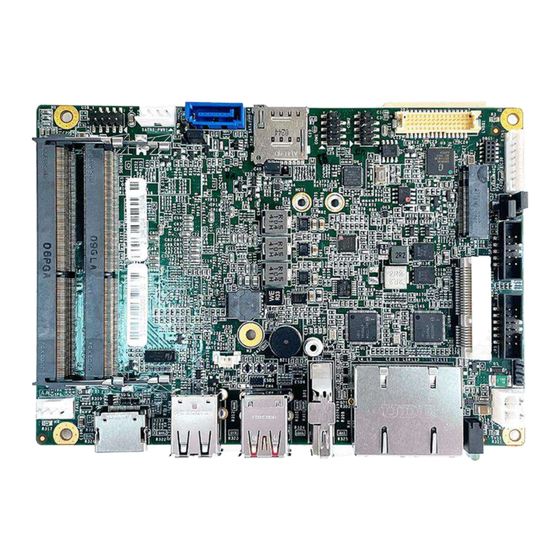
Page 12: Switch And Connector Locations
CT-DR101 l User’s Manual Chapter 2: Mechanical Specifications 2.1 Switch and Connector Locations 2.1.1 Top View DC_IN1 GPIO1 MINI_PCIE1 LVDS1 COM2 COM1 SIM2 SATA1 BAT1 SATA1_PWR1 SODIMM1 SODIMM2 HDMI1 USB_1 FAN1... - Page 13 CT-DR101 l User’s Manual Chapter 2: Mechanical Specifications 2.1.2 Bottom View 2.1.3 Rear I/O...
-
Page 14: Connector / Switch Definition
CT-DR101 l User’s Manual Chapter 2: Mechanical Specifications 2.2 Connector / Switch Definition Connector Location Definition Clear CMOS Panel PWR setting Backlight PWR setting Front Panel AT/ATX setting Panel Control M.2 B key USB 2.0 port USB 3.2 Gen 2... -
Page 15: I/O Interface Descriptions
CT-DR101 l User’s Manual Chapter 2: Mechanical Specifications 2.3 I/O Interface Descriptions 2.3.1 Clear CMOS Signal RTCRST# 2.3.2 Panel Power setting Signal +V3.3A P3P5V +V5A... -
Page 16: Backlight Power Setting
CT-DR101 l User’s Manual Chapter 2: Mechanical Specifications 2.3 I/O Interface Descriptions 2.3.3 Backlight Power setting Signal +V12A P5P12V +V5A... -
Page 17: Front Panel Header
CT-DR101 l User’s Manual Chapter 2: Mechanical Specifications 2.3 I/O Interface Descriptions 2.3.4 Front Panel Header Signal Signal Power(3.3V) SATA_LED# Power(3.3V) LOUT_R RESET_BUTTON_N LOUT_L PS_ON_BUTTON_N MICIN1_R MICIN1_L AGND_HD... -
Page 18: At/Atx Setting
CT-DR101 l User’s Manual Chapter 2: Mechanical Specifications 2.3 I/O Interface Descriptions 2.3.5 AT/ATX setting Signal AT MODE PS_ON_BUTTON_N... -
Page 19: Panel Control
CT-DR101 l User’s Manual Chapter 2: Mechanical Specifications 2.3 I/O Interface Descriptions 2.3.6 Panel control Signal Signal LVDS_BKLTEN LBKLT_CTRL BLPWR BLPWR CH7511_BLUP CH7511_BLDN... -
Page 20: Usb2
CT-DR101 l User’s Manual Chapter 2: Mechanical Specifications 2.3 I/O Interface Descriptions 2.3.7 USB2 Signal Signal USBVCC0 USBVCC0 USB0N_CONN USB4N_CONN USB0P_CONN USB4P_CONN... -
Page 21: Usb 3.2
CT-DR101 l User’s Manual Chapter 2: Mechanical Specifications 2.3 I/O Interface Descriptions 2.3.8 USB 3.2 Signal Signal USBVCC0 USBVCC1 USB2-2N_CONN USB1N_CONN USB2-2P_CONN USB1P_CONN USB3-RN2_CONN USB3-RN1_CONN USB3-RP2_CONN USB3-RP1_CONN USB3-TN2_CONN USB3-TN1_CONN USB3-TP2_CONN USB3-TP1_CONN... -
Page 22: Expansion I/O
CT-DR101 l User’s Manual Chapter 2: Mechanical Specifications 2.3 I/O Interface Descriptions 2.3.9 Expansion I/O Signal Signal PE1_TX+ PE3_RX- PE1_TX- PE4_TX+ PE1_RX+ PE4_TX- PE1_RX- PE4_RX+ PE2_TX+ PE4_RX- PE2_TX- USB_0P USB_0N PE2_RX+ Power_BTN PE2_RX- SYS_RST# PLTST_N SMB_DAT(3.3V) REF_CLK+ SMB_CLK(3.3V) REF_CLK- +V3.3S +V3.3S... -
Page 23: Com1 Port
CT-DR101 l User’s Manual Chapter 2: Mechanical Specifications 2.3 I/O Interface Descriptions 2.3.10 COM Port COM1 Signal Signal CM1_DCD CM1_DSR CM1_RXD CM1_RTS CM1_TXD CM1_CTS CM1_DTR CM1_RI... -
Page 24: Com2 Port
CT-DR101 l User’s Manual Chapter 2: Mechanical Specifications 2.3 I/O Interface Descriptions 2.3.11 COM Port COM2 Signal Signal CM2_DCD CM2_DSR CM2_RXD CM2_RTS CM2_TXD CM2_CTS CM2_DTR CM2_RI... -
Page 25: Gpio
CT-DR101 l User’s Manual Chapter 2: Mechanical Specifications 2.3 I/O Interface Descriptions 2.3.12 GPIO GPIO1 Signal Signal Power SIO_GPI1 SIO_GPO1 SIO_GPI2 SIO_GPO2 SIO_GPI3 SIO_GPO3 SIO_GPI4 SIO_GPO4... -
Page 26: Sata
CT-DR101 l User’s Manual Chapter 2: Mechanical Specifications 2.3 I/O Interface Descriptions 2.3.13 SATA SATA1 Signal SATA_TX0_C_DC_DP SATA_TX0_C_DC_DN SATA_RX0_DC_DN SATA_RX0_DC_DP... -
Page 27: Sata_Pwr
CT-DR101 l User’s Manual Chapter 2: Mechanical Specifications 2.3 I/O Interface Descriptions 2.3.14 SATA_PWR SATA1_PWR1 Signal +V5S +V12S... -
Page 28: Usb2.0 Header
CT-DR101 l User’s Manual Chapter 2: Mechanical Specifications 2.3 I/O Interface Descriptions 2.3.15 USB2.0 Header USB_1 Signal Signal USBVCC2 USBVCC2 USB2-5N_CONN USB2-6N_CONN USB2-5P_CONN USB2-6P_CONN... -
Page 29: Power In
CT-DR101 l User’s Manual Chapter 2: Mechanical Specifications 2.3 I/O Interface Descriptions 2.3.16 Power IN DC_IN1 Signal... -
Page 30: Fan Pwr
CT-DR101 l User’s Manual Chapter 2: Mechanical Specifications 2.3 I/O Interface Descriptions 2.3.17 FAN PWR FAN1 Signal FANCTL1 FAN_SEN1 FAN_IN1... -
Page 31: Hdmi Display
CT-DR101 l User’s Manual Chapter 2: Mechanical Specifications 2.3 I/O Interface Descriptions 2.3.18 HDMI Display HDMI1 Signal Signal HDMI_TX2+_C HDMI_TXC-_C HDMI_TX2-_C HDMI_TX1+_C HDMI_SCL HDMI_TX1-_C HDMI_SDA HDMI_TX0+_C VCC5_HDMI HDMI_TX0-_C HDMI_HPD_CON HDMI_TXC+_C... -
Page 32: Display Port
CT-DR101 l User’s Manual Chapter 2: Mechanical Specifications 2.3 I/O Interface Descriptions 2.3.19 Display Port Signal Signal ML_LANE0+ ML_LANE3- ML_LANE0- ML_LANE1+ AUX CH+ ML_LANE1- ML_LANE2+ AUX CH- ML_LANE2- DP_PWR Return ML_LANE3+ DP_PWR... -
Page 33: Dual Rj45
CT-DR101 l User’s Manual Chapter 2: Mechanical Specifications 2.3 I/O Interface Descriptions 2.3.20 Dual RJ45 Signal Signal R1 GBE1_MDI0P R1 GBE2_MDI0P R2 GBE1_MDI0N R2 GBE2_MDI0N R3 GBE1_MDI1P R3 GBE2_MDI1P R4 GBE1_MDI1N R4 GBE2_MDI1N R5 GBE0_CT R5 GBE0_CT R6 GBE0_CT R6 GBE0_CT... -
Page 34: Lvds Header
CT-DR101 l User’s Manual Chapter 2: Mechanical Specifications 2.3 I/O Interface Descriptions 2.3.21 LVDS Header LVDS1 Signal Signal LB_DATA-N3 LB_DATA-P3 LB_CLK-N LB_CLK-P LB_DATA-N2 LB_DATA-P2 LB_DATA-N1 LB_DATA-P1 LB_DATA-N0 LB_DATA-P0 MIICSDA MIICSCL LA_DATA-P3 LA_DATA-N3 LA_CLK-P LA_CLK-N LA_DATA-P2 LA_DATA-N2 LA_DATA-P1 LA_DATA-N1 LA_DATA-P0 LA_DATA-N0... -
Page 35: B Key
CT-DR101 l User’s Manual Chapter 2: Mechanical Specifications 2.3 I/O Interface Descriptions 2.3.22 M.2 B key Signal Signal CONFIG_3 VCC1 VCC2 FULL_CARD_POWER_OFF# USB_D+ W_DISABLE1# USB_D- WWAN_LED# NOTCH NOTCH NOTCH NOTCH NOTCH NOTCH NOTCH NOTCH GPIO_5(O/1.8V) CONFIG_0 GPIO_6(O/1.8V) GPIO_11(0/1.8V) GPIO_7(O/1.8V) GPIO_10(O/1.8V) GPIO_8(O/1.8V) - Page 36 CT-DR101 l User’s Manual Chapter 2: Mechanical Specifications Signal Signal PERp0/SATA-B- USIM2_CLK USIM2_RST PETn0/SATA-A- USIM2_VDD PETp0/SATA-A+ PCIE_RST_N PCIE_CLKREQ_N PCIE_REFCLK_M PCIE_WAKE_N PCIE_REFCLK_P ANTCTL0 COEX3(O/1.8V) ANTCTL1 COEX2(O/1.8V) ANTCTL2 COEX1(O/1.8V) ANTCTL3 USIM1_DET RESET_N SUSCLK(32kHz) CONFIG_1 VCC3 VCC4 VCC5 CONFIG_2...
-
Page 37: Sim Card
CT-DR101 l User’s Manual Chapter 2: Mechanical Specifications 2.3 I/O Interface Descriptions 2.3.23 SIM Card SIM2 Signal Signal DATA... -
Page 38: Battery
CT-DR101 l User’s Manual Chapter 2: Mechanical Specifications 2.3 I/O Interface Descriptions 2.3.24 Battery BAT1 Signal Signal Battery Power 2.3.25 Buzzer Signal Signal Passive Negative... -
Page 39: Memory
CT-DR101 l User’s Manual Chapter 2: Mechanical Specifications 2.3 I/O Interface Descriptions 2.3.26 Memory SODIMM1/SODIMM2 Socket... -
Page 40: Chapter 3 System Setup
Chapter 3 System Setup... -
Page 41: Heat Sink Installation
CT-DR101 l User’s Manual Chapter 3: System Setup 3.1 Heat Sink Installation Heat sink x1 Board x1 Screw x4 Top view Bottom view... - Page 42 CT-DR101 l User’s Manual Chapter 3: System Setup Heat Sink Installation (Standard) Fasten the four screws below to lock the Heat sink.
-
Page 43: Chapter 4 System Bios
Chapter 4 System BIOS... -
Page 44: Bios Introduction
CT-DR101 l User’s Manual Chapter 4: BIOS Setup 4.1 BIOS Introduction The BIOS provides an interface to modify the configuration. When the battery is removed, all the parameters will be reset. BIOS Setup Power on the embedded system and by pressing <Del> immediately allows you to enter the setup screens. -
Page 45: Main Setup
CT-DR101 l User’s Manual Chapter 4: BIOS Setup 4.2 Main Setup Press <Del> to enter BIOS CMOS Setup Utility. The Main setup screen is showed as following when the setup utility is entered. System Date/Time is set up in the Main Menu. -
Page 46: Advanced Setup
CT-DR101 l User’s Manual Chapter 4: BIOS Setup 4.3 Advanced Setup... -
Page 47: Trusted Computing
CT-DR101 l User’s Manual Chapter 4: BIOS Setup 4.3.1 Trusted Computing Item Options Description Security Device Support Enabled, Enable/Disable BIOS support for security Disabled[Default] , device. O.S. will not show Security Device.TCG EFI protocol and INT1A interface will not be available. -
Page 48: Acpi Settings
CT-DR101 l User’s Manual Chapter 4: BIOS Setup 4.3.2 ACPI Settings Item Options Description Enable Hibernation Disabled , Enables or Disables System ability to Enabled[Default], Hibernate (OS/S4 Sleep State). This option may not be effective with some operating systems. ACPI Sleep State... -
Page 49: Ide Configuration
CT-DR101 l User’s Manual Chapter 4: BIOS Setup 4.3.3 IDE Configuration... -
Page 50: Super Io Configuration
CT-DR101 l User’s Manual Chapter 4: BIOS Setup 4.3.4 Super IO Configuration This setting allows you to select options for the Super IO Configuration, and change the value of the selected option. Item Description Serial Port 1 Configuration Set Parameters of Serial Port 1 (COMA). - Page 51 CT-DR101 l User’s Manual Chapter 4: BIOS Setup ■ Serial Port 1 Configuration Item Options Description Serial Port Disabled, Enable or Disable Serial Port (COM). Enabled[Default] Change Settings Auto[Default], This item allows you to change the IO=3F8h; IRQ=4; , address & IRQ settings of the specified IO=3F8h;...
- Page 52 CT-DR101 l User’s Manual Chapter 4: BIOS Setup ■ Serial Port 2 Configuration Item Options Description Serial Port Disabled, Enable or Disable Serial Port (COM). Enabled[Default] Change Settings Auto[Default], This item allows you to change the IO=2F8h; IRQ=3; , address & IRQ settings of the specified IO=3F8h;...
-
Page 53: Hardware Monitor
CT-DR101 l User’s Manual Chapter 4: BIOS Setup 4.3.5 Hardware Monitor These items display the current status of all monitored hardware devices/ components such as voltages and temperatures. Item Options Description Smart Fan Function Disabled[Default], Enabled or Disable Smart Fan... - Page 54 CT-DR101 l User’s Manual Chapter 4: BIOS Setup ■ Smart Fan Mode Configuration Item Options Description SYS Fan SmartFan Manual Mode, Smart Fan Mode Select Control Thermal Cruise Mode, SMART FAN IV Mode[Default], Temperature 1~4 1~100 Auto fan speed control. SMART FAN IV...
-
Page 55: Serial Port Console Redirection
CT-DR101 l User’s Manual Chapter 4: BIOS Setup 4.3.6 Serial Port Console Redirection Item Options Description Console Redirection Disabled[Default], These items allows you to enable or Enabled disable COM1 console redirection... - Page 56 CT-DR101 l User’s Manual Chapter 4: BIOS Setup Console Redirection Settings Item Options Description Terminal VT100 Emulation: ANSI: Extended ASCII char set. VT100: ASCII char set. VT100+: Type VT100+, Extends VT100 to support color, function keys, etc. VT-UTF8: Uses UTF8 VT-UTF8, encoding to map Unicode chars onto 1 or more bytes.
-
Page 57: Cpu Configuration
CT-DR101 l User’s Manual Chapter 4: BIOS Setup 4.3.7 CPU Configuration Item Options Description PSS Support Disabled, Enable/disable the generation of ACPI _PPC, Enabled[Default] _PSS, and _PCT objects. NX Mode Disabled, Enable/disable No-execute page protection Enabled[Default] Function SVM Mode Disabled,... -
Page 58: Usb Configuration
CT-DR101 l User’s Manual Chapter 4: BIOS Setup 4.3.8 USB Configuration Item Options Description Legacy USB Enabled[Default] Enables Legacy USB support. AUTO option Support Disabled disables legacy support if no USB devices are Auto connected. DISABLE option will keep USB devices available only for EFI applications. -
Page 59: Network Stack Configuration
CT-DR101 l User’s Manual Chapter 4: BIOS Setup 4.3.9 Network Stack Configuration Item Options Description Network Stack Disabled[Default] , Enable/Disable UEFI Network Stack. Enabled IPv4 PXE Support Disabled[Default] , Enable/Disable IPv4 PXE boot support. If Enabled disabled, IPv4 PXE boot support will not be available. -
Page 60: Csm Configuration
CT-DR101 l User’s Manual Chapter 4: BIOS Setup 4.3.10 CSM Configuration Item Options Description CSM Support Disabled[Default] , This item allows users to enable or disable for “CSM Enabled Support”. GateA20 Active Upon Request[Default] , This item allows users to set Upon Request or Always for Always "GateA20 Active“. -
Page 61: Amd Cbs
CT-DR101 l User’s Manual Chapter 4: BIOS Setup 4.3.11 AMD CBS Item Options Description AC Loss Control Power Off[Default] , Specify what state to go to when power is Power On, re-applied after a power failure (G3 state). Last State... -
Page 62: Chipset
CT-DR101 l User’s Manual Chapter 4: BIOS Setup 4.4 Chipset This section allows you to configure and improve your system and allows you to set up some system features according to your reference. 4.4.1 SB USB Configuration Item Options Description... -
Page 63: North Bridge Configuration
CT-DR101 l User’s Manual Chapter 4: BIOS Setup 4.4.2 North Bridge Configuration Item Options Description Control LVDS Disabled[Default], Enabled/Disabled LVDS Enabled... -
Page 64: Security
CT-DR101 l User’s Manual Chapter 4: BIOS Setup 4.5 Security Security menu allow users to change administrator password and user password settings. ■ Administrator Password This item allows you to set Administrator Password. ■ User Password This item allows you to set User Password. - Page 65 CT-DR101 l User’s Manual Chapter 4: BIOS Setup ■ Security Boot Item Options Description Secure Boot Disabled [Default] , Secure Boot feature is Active if Secure Boot is Enabled Enabled,Platform Key(PK) is enrolled and the System is in User mode.
- Page 66 CT-DR101 l User’s Manual Chapter 4: BIOS Setup ■ Key Management Item Options Description Factory Key Disabled [Default] , Install factory default Secure Boot keys Provision Enabled after the platform reset and while the System is in Setup mode...
-
Page 67: Boot
CT-DR101 l User’s Manual Chapter 4: BIOS Setup 4.6 Boot This menu allows you to setup the system boot options. Item Options Description Setup Prompt 1[Default] Number of seconds to wait for setup activation Timeout key. 65535(0xFFFF) means indefinite waiting. -
Page 68: Save And Exit
CT-DR101 l User’s Manual Chapter 4: BIOS Setup 4.7 Save & Exit This setting allows users to configure the boot settings. ■ Save Changes and Reset This item allows user to reset the system after saving the changes. This item allows user to reset the system after saving the changes. -
Page 69: Appendix Wdt & Gpio
Appendix WDT & GPIO This appendix provides the sample codes of WDT (Watch Dog Timer) and GPIO (General Purpose Input/ Output). -
Page 70: Wdt Sample Code
Appendix – WDT & GPIO CT-DR101 l User’s Manual WDT Sample Code WDT Setting Psuedo Code UINT8 WDT_TimeOut_Sec=2; //Second value //Set Second Number *(volatile UINT32 *)0xFEB00000= 0x03; //Initialization WatchdogControl IoWrite8(0x80,0xFF); //Delay time *(volatile UINT32 *)0xFEB00004= WDT_TimeOut_Sec; //Set watch dog time value(Bit15~Bit0) IoWrite8(0x80,0xFF);... -
Page 71: Gpio Sample Code
The GPIO function is provided by Nuvoton NCT6106D, and it can be accessed through its GPIO index/data port. To access the GPIO register, write index to the index port, and then read/write from/to data port. The configuration on the CT-DR101 is described as below. - Page 72 © 2022 Premio Inc. All Rights Reserved www.premioinc.com...
Need help?
Do you have a question about the CT-DR101 and is the answer not in the manual?
Questions and answers