
Related Manuals for Comet Commeter D3121P


Summary of Contents for Comet Commeter D3121P
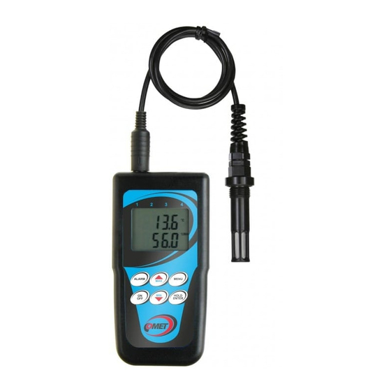
- Page 1 Instruction manual Commeter D3121P Digital thermometer-hygrometer and datalogger for compressed air measurement...
-
Page 2: Table Of Contents
Table of contents GENERAL DESCRIPTION ......................3 TECHNICAL PARAMETERS ......................4 Measured and calculated values .................... 4 General ..........................5 Operation conditions ......................6 Dimensions ..........................8 OPERATION OF THE DEVICE ....................... 9 Switching ON and OFF the device ..................9 Displaying of actual measured values .................. -
Page 3: General Description
General description Instrument is designed for measurement and logging temperature and relative humidity of the compressed air with the possibility of displaying the dew point temperature. Measured values are displayed on a dual line LCD display and it is possible to store values into the non volatile memory. Then it is possible to transfer data to a personal computer. -
Page 4: Technical Parameters
Technical parameters Measured and calculated values Temperature: Measuring range: -30 to +105 °C Resolution: 0.1 °C Accuracy: ±0.4 °C Response time t90 < 9 min with sensor cover with filter from stainless steel mesh _____________________________________________________________________________________________________________________ Air flow approximately 1m/s, temperature step 20 °C Relative humidity: Measuring range: 0 to 100 %RH... -
Page 5: General
General Measuring interval and display reading refresh approximately: 0.7 s in FAST mode 0.7 to 5 s in dynamic mode Logging interval: 10 s to 24 h (in automatic logging mode) Total memory capacity: 1000 sets of all input quantities manual logging mode 8124 values automatic noncyclic logging mode... -
Page 6: Operation Conditions
Electromagnetic compatibility: Device conforms in accordance with EN 61326-1 these norms: Radiation: EN 55022 class B Immunity: EN 61000-4-2 (levels 4/8 kV, class A) EN 61000-4-3 (intensity of electromagnetic field 3 V/m, class B) EN 61000-4-4 (levels 1/0.5 kV, class A) EN 61000-4-6 (intensity of electromagnetic field 3 V/m, class B) EN 61000-4-11 (class A) - Page 7 Operating pressure range of the probe: Up to 25 bar Air flow velocity: Up to 25 m/s at a pressure of 1 bar (1 m/s at a pressure of 25 bar) Mechanical connection of probe: G1/2 with O-ring Working position of the probe: Vertical with the cover downwards Not allowed manipulation: ...
-
Page 8: Dimensions
Dimensions IE-COM-D3121P-05... -
Page 9: Operation Of The Device
Operation of the device Switching ON and OFF the device Switch ON the instrument by pressing ON/OFF key. After switching ON the instrument all symbols on the LCD are displayed. If the ON/OFF key is being held pressed, all LCD symbols are displayed till the key is released. -
Page 10: Function Hold (Storing Of Actual Measured Values) And Minimum A Maximum Memory
Function HOLD (storing of actual measured values) and minimum a maximum memory Press HOLD key in the default mode (displaying of actual measured value) to store actual measured values to internal memory (indicated by short beep). Anytime it is possible to display stored values from MENU (see below). - Page 11 This item indicates if audio signaling of alarm indication is switched on (On) or switched off (OFF). Press ENTER key to change actual setting. Notice: if the battery voltage is low, audio indication is out of operation to reduce current consumption independently on this selection. Clearing of minimum and maximum memory of all values.
-
Page 12: Alarm Indication And Setting
Alarm indication and setting It is possible to set lower and upper limit for each measured quantity. Breaking of the limit is indicated by blinking of the appropriate value on the display. If a new alarm was indicated (i.e. it was not active in the previous measurement), display starts to display the value out of limits. -
Page 13: Logging Mode
Logging mode In logging mode measured values are stored to instrument internal memory. Memory is non volatile, i.e. if battery voltage drops or battery is disconnected, stored data will not be lost. Device can work in two logging modes: Automatic mode – actual measured values are stored to memory in adjustable time interval. Storing of the first value is synchronized with internal real time clock, so the memorizing is performed at sharp multiples of minutes, hours and days. -
Page 14: Logging Start With Clearing Memory And Logging Mode Selection
Instrument offers the possibility to clearing the instrument memory (ERAS). If you do not wish to clear the memory before new logging start, confirm selection ERAS NO by pressing the ENTER key. Now instrument displays adjusted storing interval. To modify the storing interval use arrow keys. -
Page 15: Logging Stop From Keyboard
Clearing procedure is in progress. The duration is indicated by displaying of already cleared memory in % (digits 0 to 100). After memory is cleared it is possible to select one of three logging modes (MODE) by using arrow keys (non cyclic logging is indicated by symbol n.CYC, cyclic logging by symbol CYCL and manual logging by symbol Man). -
Page 16: Connection Of The Device To A Personal Computer
Connection of the device to a personal computer For connection of the instrument to a personal computer is designed the USB communication cable (included in delivery). During time instrument is connected to the computer, there is a reading PC on the LCD display and measurement nor logging is interrupted. Keyboard of the instrument is disabled with the exception of ON/OFF key. -
Page 17: The Pc Software For The Device
Visit www.cometsystem.com and click to link Programs. Download Program for dataloggers Comet to your computer. After running downloaded file logger.exe follow the Installator instruction. • Installation from installation CD: Insert installation CD to CD-ROM drive and wait for automatic Installator run. If Installator is not run automatically (depends on setting of operating system), find in file browser file CDSetup.exe in main directory of the installation CD and click to run. - Page 18 Viewing of measured values Measured values can be read directly from datalogger or from formerly created file on disk (command File - From disk, key F3). After reading a table of measured values occurs. Detailed information on file is available from context menu - menu occurs after clicking right mouse button on the position of table.
-
Page 19: Battery Replacement
Battery replacement If battery voltage is low logging mode of the instrument is disabled. Low battery voltage is indicated on the display with blinking reading "BAT". It is necessary to replace it with new one as soon as possible. Battery is located under small cover on the instrument lower side. It is absolutely necessary to replace battery with instrument switched OFF, otherwise internal time and setting of d.REF. -
Page 20: Technical Support And Service
Technical support and service Technical support and service is provided by distributor. Contact is included in warranty certificate. Distributor in Australia & New Zealand Pacific Sensor Technologies Pty Ltd Unit 4, 3 Neutron Place Rowville, VIC 3178 Australia 1300 662 720 | sales@pacificsensortech.com.au www.pacificsensortech.com.au IE-COM-D3121P-05... - Page 21 Appendix A The probe for measuring the moisture of compressed air should be placed directly on the pressure pipelines to achieve higher measurement accuracy and fast response times. But they are cases where such placement is not possible. The reason is the high air speed, high temperature, high pollution, small diameter pipes, etc.
Need help?
Do you have a question about the Commeter D3121P and is the answer not in the manual?
Questions and answers