
Related Manuals for Comet MS5


Summary of Contents for Comet MS5
-
Page 1: Instruction Manual
MONITORING, DATA LOGGING AND CONTROL SYSTEM MS5, MS5D INSTRUCTION MANUAL Basic Part SYSTEM s.r.o. -
Page 2: Table Of Contents
7.13. Problems with correct measurement ................48 7.14. Problems in communication with computer ..............49 8. RECOMMENDATION FOR OPERATION AND MAINTENANCE........50 9. TECHNICAL DESCRIPTION AND PARAMETERS OF DATA LOGGER ......52 Note: Manual Appendixes are available in electronic pdf format. ie-ms2-MS5-02... -
Page 3: Introduction
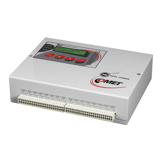
SMS message, controlling of telephone dialer etc.) • to monitor on-line measured values and states The basic model is data logger MS5. Data logger MS5D is equipped on the top of it with and display and simple keyboard. Drawing (MS5D): Items marked Accessory are not included in delivery and it is necessary to order separately. - Page 4 Architecture of measuring system with data logger MS5: ie-ms2-MS5-02...
-
Page 5: General Safety Precautions
SW in part Configuration – Configuration of data logger (icon i). Detailed description of data logger configuration is in part DESCRIPTION of CONFIGURATION and MODES of DATA LOGGER. • set data logger Name, Date and Time in data logger ie-ms2-MS5-02... - Page 6 – Display mode, enables to watch simultaneously all connected data loggers • Display mode can be shared simultaneously on several computers in the network Instructions for regular check and maintenance of data logger are specified in part RECOMMENDATIONS for OPERATION and MAINTENANCE. ie-ms2-MS5-02...
-
Page 7: Rules For Mounting And Connection Of Data Logger
The way of mounting of consoles to data logger and mounting holes dimensions: • data logger is fixed by means of the holder on DIN rail at low current switchboard - working position is with input connectors downward The way of mounting the holder to data logger: ie-ms2-MS5-02... - Page 8 In cable routing follow rules of standards for installation of low current distribution (EN 50174-2), especially it is necessary to pay attention to avoid electromagnetic interference intrusion to the leads, transmitters, transducers and sensors. Do not locate cabling near sources of interference. ie-ms2-MS5-02...
- Page 9 - do not connect cable shielding at end device side, if these device do not have terminal designed for shielding. Shielding must not be connected to outer metal parts of the device nor with other devices. Do not use shielding as a signal lead. ie-ms2-MS5-02...
- Page 10 Do not use common leads for several channels • It is recommended to earth data logger at one point – there is a special terminal on power terminal. This earthing will work correctly, if system would not be grounded at other point at the same time. ie-ms2-MS5-02...
-
Page 11: Data Logger Interface Connectors
All inserted devices must be galvanic isolated from other circuits. In case, it is not possible to ensure this, use galvanic isolated inputs A1G and power loops from external source. Connection of input part of the module A0 including connection to two-wire probes is described in appendix ie-ms2-MS5-02... - Page 12 Activity of this output can be cancelled from data logger keyboard by the user or remotely from the PC. It is enabled to identify by proper data logger configuration, who cancelled the alarm. It is possible to connect to this output: ie-ms2-MS5-02...
-
Page 13: Mounting And Connection Of Output Relays Module Mp018
Pay attention to necessary safety (depending on the character of connected device). Configuration: Activate relay module function for proper operation in service menu of user SW. If data logger is delivered together with relay module, this function is activated already from the manufacturer. Relay module layout: ie-ms2-MS5-02... -
Page 14: Mounting And Connection Of External Terminal With Display
ALARM OUT. This function can be enabled or disabled in service menu of the 3.5. Connection of data logger to the computer Data logger contains for communication with computer one internal communication interface, which is separated to several external interfaces: ie-ms2-MS5-02... - Page 15 Before Setting of communication in user SW it is necessary to connect converter physically to the computer to allow operating system to create virtual communication port. Drivers are installed to your computer during installation of user SW for data logger (valid for Windows 2000 and higher). ie-ms2-MS5-02...
- Page 16 Near data logger Ethernet network socket is available. Connection cable is not included in delivery • data logger configuration and data download is not enabled simultaneously for several users 3.5.4 Connection of data loggers to the computer by means of interface RS485 Parameters: ie-ms2-MS5-02...
- Page 17 This configuration can be changed both from user SW and directly from the data logger keyboard. • do not connect to network of data loggers MS5 RS485 any other device, than data logger MS5, MS2+, MS3+ or MS4+ ie-ms2-MS5-02...
- Page 18 Drawing of connection by means of converter RS232/RS485 (recommended type E06D): Drawing of connection by means of converter USB/RS485 (recommended type: E214): ie-ms2-MS5-02...
- Page 19 Detailed description is specified in the following chapter with the description of Configuration of communication. • connect interface RS232 of data logger with modem by cable, delivered with modem ! • Used SIM card must enable data transfers (verify at your operator, not every operator automatically supports). ie-ms2-MS5-02...
-
Page 20: Wiring Of Data Logger With Supported Sms Messages
SMS port must be connected to GSM modem (recommended type Wavecom M1306B), use original connection cable delivered with modem • modem must contain SIM card enabling transfer of SMS messages. Must not be blocked by PIN code • area must be covered by GSM signal Drawing of connection: ie-ms2-MS5-02... -
Page 21: Connection Of Data Logger To Power
4.2. Installation of program Insert disk with programs for Comet instruments to the CD drive and run program setup.exe. Installation wizard appears to perform all installation. Run installed program from menu Start-Program files-CometLoggers-MSPlus (if you did not change its location during installation). - Page 22 In the next window select number of COM port and enter your name of the device (selectable, from letters and digits) • Confirm window and choose selection Search. Program goes through all used communication speeds and displays found data loggers in bottom window part (Dataloggers). Finally confirm window Setting of communication (OK). ie-ms2-MS5-02...
- Page 23 • check on display of data loggers, if the same communication speed and different addresses are set • In the software select menu item Configuration –Communication settings and continue in options New communication device - Net serial ie-ms2-MS5-02...
- Page 24 Used converter must support interface RS485 and be switched to interface RS485! • Confirm window and enter selection Search. Program goes through all addresses and displays found data loggers in the bottom window part (Dataloggers). Finally confirm window Communication settings (OK). ie-ms2-MS5-02...
- Page 25 In the next window select number of COM port, where modem is connected and enter your name of the device (selectable, from letters and digits). Some modem types work only on speed 9600 Bd. • confirm window and in part Dataloggers enter selection New, select communication device and enter telephone number of modem at data logger ie-ms2-MS5-02...
-
Page 26: Basic Items In Menu Program
• Event viewer – here actions are stored run by the SW with data logger and theirs result Item menu Configuration: • Datalogger settings – detailed description will follow • Erase datalogger memory – after confirmation erasing is performed ie-ms2-MS5-02... -
Page 27: Description Of Configuration And Data Logger Modes
Processes. More detailed description is specified in chapter Application notes. • if you will need to swap between different configurations during data logger operation, use Profiles. More detailed description is specified in chapter Application notes. ie-ms2-MS5-02... -
Page 28: Bookmark Communication
Sending of traps - if ticked, warning SNMP traps will be sent to below specified addresses SysLog - if ticked, warning messages will be sent to below address of SysLog server Web enabled – if ticked, www pages of data logger will be created ie-ms2-MS5-02... -
Page 29: Bookmark Profile
Recepient of e-mails 1-3 - e-mail addresses of recepients. E-mails will be sent to those adresses in case of selected alarms Sender - enables to set addresses of the e-mail sender. Selection Original sender sets sender name to MS5@IP address Send testing e-mail - sends testing e-mails to selected addresses Bookmark SNMP: Recepient of trap 1 –... -
Page 30: Bookmark Ch
Processes (except binary inputs) – allow which processes are enabled to use. See Application notes. • Show increments (only CTU, CTK inputs) – LCD displays always absolute, resp. converted absolute counter value. It is enabled to display in record table only increments between consequent measurements in accordance with adjusted logging interval. ie-ms2-MS5-02... -
Page 31: Bookmark Ch
Profile. Example of measured values list (condition for record – temperature is higher than 40°C): Date and time Channel 10: T[°C] 1.1.2004 10:55:00 40,1 1.1.2004 11:00:00 41,3 1.1.2004 11:05:00 40,2 1.1.2004 11:30:00 40,3 1.1.2004 11:35:00 42,5 1.1.2004 11:40:00 40,1 ie-ms2-MS5-02... - Page 32 Condition or Combination of conditions, use this selection. Work with conditions is similar as in previous case. Always time and value is stored when defined state of conditions started or was terminated. Example table with sampled record: Date and time Channel 1: T[°C] 1.1.2004 08:01:11 23,8 ie-ms2-MS5-02...
-
Page 33: Bookmark Ch
(till change of data logger configuration). You can select validity termination after value return back with hysteresis (2) OR (optionally AND) if defined time expired (maximum 65535 s). You can also define, how the state of the condition works if measurement error appears: ie-ms2-MS5-02... - Page 34 4. if power of data logger is switched OFF in area 3 or 4, after switching ON measured value is over limit decreased of hysteresis, condition stays valid. But if measured value does not match this, condition is invalid immediately. Other examples of configuration of conditions depended on measured value: • Setting of condition validity at measured value drop: ie-ms2-MS5-02...
- Page 35 • Condition with fixed specified time validity ie-ms2-MS5-02...
- Page 36 3600s condition valid condition invalid To renew validity of condition measured value first must drop below specified limit and then to exceed the limit. • Combination of condition validity termination with hysteresis OR after specified delay ie-ms2-MS5-02...
- Page 37 3600s condition valid condition invalid To renew validity of condition measured value first must drop below specified limit and then to exceed the limit. Combination of condition validity termination with hysteresis AND after specified delay ie-ms2-MS5-02...
-
Page 38: Bookmark Ch
Two alarm states for each channel are enabled to define. Several actions are enabled to assign to each alarm. Alarms are defined based on validity of Conditions or based on logical Combinations of conditions (maximum four conditions from different channels). Wiring diagram of possibility of alarm states creation and associated actions: ie-ms2-MS5-02... - Page 39 Alarm is active, if input conditions are valid. By means of combination of conditions you can solve also complex situations including remote control. Some actions last during all alarm time (audible indication, ALARM OUT output activity, visual indication, relay closing), other actions last only at the moment of alarm creation (SMS message, e-mails). ie-ms2-MS5-02...
-
Page 40: Control And Indication Components Of Data Logger
Error message can occur instead of measured value. Binary inputs display at the whole LCD bottom line user defined ENTER MENU description of state closed/open. In case value is not available or is not correct error message is displayed – see Appendix 7. ie-ms2-MS5-02... - Page 41 Press MENU key in basic display to enter the data logger Menu. keys to go through all menu items. Press MENU key to leave menu to the basic display. Menu item >>> ENTER MENU one step another menu enter to item submenu back ie-ms2-MS5-02...
- Page 42 ENTER key to confirm the selection. This selection is 115200 Bd not available for some communication interface. ATTENTION – standard computer COM port does not support communication speed 230 400 Bd. This highest speed MENU ENTER you can use at USB connection. ie-ms2-MS5-02...
- Page 43 Press ENTER key to enter selection of configuration profiles. By means of keys select new profile and confirm by Select config.: pressing ENTER key. This action also causes reset of all Profile 1 conditions, which were created or were preparing to be created. ENTER MENU ie-ms2-MS5-02...
- Page 44 -6V) and third value is voltage of internal back-up battery (2,6V to 3,3 V). ENTER MENU Service – display of firmware version and uP speed Firmware ver.: 5.2.1 6MHz ENTER MENU Service – display of cold junction temperature of thermocouple Cold junction: 25.5 [°C] ENTER MENU ie-ms2-MS5-02...
-
Page 45: Application Notes
PC each time section of the record will be described with name of process, which was active in specified time • by short pressing of ENTER key on data logger it is possible to display actually active process ie-ms2-MS5-02... -
Page 46: Configuration Profiles And How To Work With
1h, 2h, 3h, 4h, 6h, 8h, 12h, 24h. Storing is performed always in whole number multiples of above intervals. E.g. if data logger is switched on at 5:05 and the interval is set to 1 hour, first data are stored at 6:00, next ie-ms2-MS5-02... -
Page 47: Identification Of Person, Who Deactivated Alarm
Restart the computer. A while after user MS program would run with Display mode. • Go over another computer and in internet browser to the Address filed enter computer name you have noted before. You would see www pages with actual measured values. ie-ms2-MS5-02... -
Page 48: How To Ensure Alarm Report, In Case Of Power Failure
20 mA in user calibration if current loop is open -30 to 60 -52,5 or Error1 -30 to 80 -57,5 or Error1 -50 to 30 -70,0 or Error1 0 to 150 -37,5 or Error1 0 to 100 -25,0 or Error1 ie-ms2-MS5-02... -
Page 49: Problems In Communication With Computer
Set communication interface RS232 from the data logger display, disconnect Ethernet cable from data logger and connect data logger to the computer via RS232 cable. If communication works properly, proceed in accordance with Appendix 9. If does not work probably service check will be necessary. ie-ms2-MS5-02... -
Page 50: Recommendation For Operation And Maintenance
B) verification of alarms – change input value to activate alarm and check on display and also in external audio indication (if used) C) evaluate in data logger if relay contacts live D) evaluate internal battery – third value in self test must be at least 2.6 V ie-ms2-MS5-02... - Page 51 Placing out of operation after end of device life Disconnect the power cord and return data logger to the supplier or specialized company. Notice: data logger contains back-up Lithium battery on motherboard and on each counter input module (CTU, CTK) ie-ms2-MS5-02...
-
Page 52: Technical Description And Parameters Of Data Logger
Module contains 16 mains relay with switching-over contacts connected to self-locking Wago terminal on the module. Each relay has three terminals available. Maximum voltage on the contact: 250 V AC Maximum current through the contact: Maximum switching power: 2000 W Mechanical life of relay contact: 3 x 10 cycles ie-ms2-MS5-02... - Page 53 10/100 MBit Ethernet Connector: RJ45 Galvanic isolation is not designed for safety function - protection against electrical current injury! the way of communication Setting of communication serial link, 1 start bit, 8 data bits, 1 stop bit, without parity ie-ms2-MS5-02...
- Page 54 2000 m above sea level influence of other elements negligible influence of radiation negligible influence of sun radiation negligible qualification of persons – knowledgeable materials without fire danger in the object Settling time after switching ON: 15 minutes ie-ms2-MS5-02...
- Page 55 Current in short circuit of input terminals: limited to approximately 25 mA Voltage across open terminals: voltage source - 3V, at power 24V approximately 21V Input module type A1 and A1G Measured value: dc current Range: (4.. 20) mA ie-ms2-MS5-02...
- Page 56 ± 100 V maximum (from safety aspect 75 V maximum) Input module type D5 and D5G Measured value: dc voltage Range: (-10.. +10) V Accuracy: 0.1 % from range (± 20 mV) Input resistance: >1 MΩ (D5), >400 kΩ (D5G) ie-ms2-MS5-02...
- Page 57 >10 MΩ Overload capacity: 5 V maximum Input module type E2 Measured value: ac voltage Range: (0.. 10) V Accuracy: 1 % from range (± 100 mV) Input resistance: >1 MΩ Overload capacity: 50 in maximum Input module type E4 ie-ms2-MS5-02...
- Page 58 Input module type K3 Measured value: temperature from resistance sensor Pt1000/ 3850 ppm Range: (-10 .. 50) °C Accuracy (without ±0.06 °C probe): Measuring current: approximately 0,2 mA (depends on temperature) Maximum voltage on ± 5 V maximum input: ie-ms2-MS5-02...
- Page 59 Counter inputs are designed for counting of incoming pulses (gas meters, electrometers..). Modules contain own processor unit, which registers incoming pulses even if power is switched OFF (module has its own battery for power, if data logger is not switched ON). Record is performed similarly as with analog ie-ms2-MS5-02...
- Page 60 0 to 5 kHz, duration of input pulse minimum 30 µs Range: Resolution: 1 Hz Accuracy: ± (0,2% from reading +1Hz) Input level: state „L“: 0 to 0,8 V state „H“: 3 to 24 V maximum Input current: approximately 7 mA in state „H“ ie-ms2-MS5-02...
- Page 61 210 ms. After waiting time error of communication is reported and reading of next channel continues. If device responses in adjusted time, response is evaluated and also reading of next channel continues. Note: for more information see Appendix 3. ie-ms2-MS5-02...
Need help?
Do you have a question about the MS5 and is the answer not in the manual?
Questions and answers