
Related Manuals for Comet U2422


Summary of Contents for Comet U2422
- Page 1 User‘s Guide U0110 U0111 U0121 U0122 U0141 U0541 U2422 U3120 U3121 U3430 U3631 U4130 U4440 U5841 U6841 U7844 U8410 USB Datalogger...
- Page 2 All rights reserved. The COMET SYSTEM, s.r.o. company is continuously developing and improving its product. COMET SYSTEM, s.r.o. reserves the right to carry out technical changes in equipment or product without any previous notice. Contact address of this device’s producer: COMET SYSTEM, s.r.o.
-
Page 3: Table Of Contents
Displaying the device data ............10 Menu Options ................14 MODELS PRODUCED ................15 COMET VISION PROGRAM ..............27 SETTING UP THE DEVICE ..............28 How to set up the device by means of a program ......28 The device setup from a program (Configuration) ....... 28 APPLICATION NOTES ................ -
Page 4: Introduction
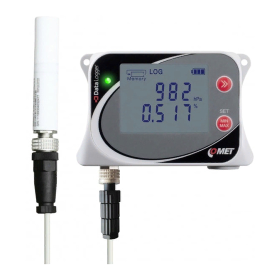
Introduction This datalogger is designed for autonomous measurements and recording of physical and electrical data, with the data recording interval from 1 s to 24 h. The inputs and ranges of quantities to be measured are determined by the model type the user has bought. The user cannot modify them. - Page 5 General view of a Uxxxx series datalogger (U0141 model): IE-LGR-Uxxxx-06...
-
Page 6: Safety Measures And Unauthorized Manipulations
Safety measures and unauthorized manipulations Read the following safety directions carefully before putting the device into operation. Follow these instructions when using the device! • Operating and storage conditions. Observe the recommended operating and storage condition as quoted in the Technical parameters. Models with a CO sensor containing an internal lithium-ion accupack should not be exposed to temperatures above 60 °C Do not expose the device to direct radiation of heat sources and sun. -
Page 7: Guide To Installation And Usage Of The Device
Guide to installation and usage of the device Installing the datalogger, placing the probes • Choose a suitable location for installing the device - bear in mind that the environmental conditions should be concordant with the Operating conditions. Do not situate the device near sources of electromagnetic interference. -
Page 8: Device Set-Up
USB cable provided with a USB-C terminal • Setting up the device - with the aid of the COMET Vision program, set up the device identification, the names of the points to be measured, the recording mode, the alarms and there signalling •... -
Page 9: Running The Device
Running the device • After the set-up - Disconnect the device from the computer and close the USB connector with a closing cap. Check that all connectors are tightened properly. The device may be operated with a permanently connected USB cable. In this case the ingress protection will be reduced to IP 20. -
Page 10: Operating The Datalogger From The Keypad
Operating the datalogger from the keypad Displaying the device data Data memory occupancy - this display section offers information about the current condition of the free space existing in the data memory. The blinking of the Memory symbol indicates that the pre-set memory occupancy limit has been exceeded. - Page 11 Record status - offers information on whether the recording is ON and whether it is just running. A continuous recording with a preset interval is ON and running. The recording is ON in the device and it is running at present. This kind of display is utilized, when the record activity is dependent on the alarm or the external input condition.
- Page 12 Battery condition - this symbol provides overview information about the current battery charging condition. The charging is indicated by flashing one of these symbols. Battery conditions during battery operation of the device: Fully charged battery Partly discharged battery Heavily discharged battery Totally discharged battery, the device will be switched OFF.
- Page 13 value of a particular channel will be displayed in the lower or upper display unit row. On the other hand, the user has many possibilities to adjust the appearance and behaviour of individual „screens“. Controlling them can take place only manually by the aid of push buttons situated beside the display unit.
-
Page 14: Menu Options
Menu Options The menu can be entered by pressing a combination of both keys. In any case, using the keypad must be enabled in the device configuration. Individual menu items, too, may be disabled in the device setup. It is e. g. possible to switch on the device in this way, but it is not possible to switch it off. -
Page 15: Models Produced
Models produced The models produced differ from one another by types and ranges of values to be measured. The datalogger’s input channels are invariably assigned to these values. The user cannot change the type and range of the values to be measured. U0110 One-channel thermometer This model is equipped with only one internal... - Page 16 For this reason, the measurement of CO2 concentration does not occur as often as the measurement of other variables. By default, this is 2 minutes with the option of extending up to 10 minutes (option available in the COMET Vision software). IE-LGR-Uxxxx-06...
- Page 17 Thermometer - hygrometer for external probe This model measures temperature, relative humidity and dew point temperature using an outdoor COMET Digi/E series probe. Its response to the temperature or relative humidity jump is significantly faster than by models with internal sensor. This model is often utilized to monitor areas in which only the probe is installed, whereas the main unit is installed elsewhere.
- Page 18 By default, this is 2 minutes with the option of extending up to 10 minutes (option available in the COMET Vision SW). We recommend calibration of the relative humidity...
- Page 19 U3631 Compact thermometer - hygrometer with optional external temperature probe This model is designed to measure temperature, relative humidity and dew-point temperature by internal sensor, moreover one additional external temperature probe Pt1000/E can be connected. Internal sensors are located under the grid on the front of the unit and are protected with Teflon foil.
- Page 20 U4130 Compact thermometer - hygrometer - pressure gauge This model is designed to measure temperature, relative humidity, dew-point temperature barometric pressure by internal sensors. Barometric pressure can be measured as absolute or recalculated to sea level. additional probes or sensors can be connected. It is characterized by a simple and compact design and a relatively long response in the measured quantities, compare to model with external probes.
- Page 21 By default, this is 2 minutes with the option of extending up to 10 minutes (option available in the COMET Vision software). We recommend that calibration of this device in the laboratory be carried out with sufficient air flow...
- Page 22 U0541 Two-channel thermometer for external probes with 2 inputs 0-10 V This model can measure up to two temperature values, which are sensed by outdoor Pt1000/0 series probes. In addition, it has two voltage inputs for monitoring voltage signal changes. Input signals are connected to a connecting block.
- Page 23 U5841 Datalogger with 3 inputs 0 - 10 V and 1 binary input This model is used to measure up to three voltage inputs 0 – 10 V DC while allowing one binary input to be monitored. The voltage inputs are not galvanically separated from one another.
- Page 24 U6841 Datalogger with 3 inputs 0 - 20 mA and 1 binary input This model is used to measure up to three signals from current loops (0 to 20) mA DC while allowing one binary input to be monitored. The current inputs are passive and are not galvanically separated from one another.
- Page 25 U7844 Two-channel binary-input counter This model includes four inputs. Two of them can function as counters, and all four inputs can function as binary inputs. Both counter and binary inputs serve to monitor voltage signals or signals coming from a voltage-free contact. The binary input changes are registered immediately, irrespectively of the recording interval setting.
- Page 26 By default, this is 2 minutes with the option of extending up to 10 minutes (option available in the COMET Vision software). Due to low IP20 protection, this device is not suitable for dusty or water-borne areas.
-
Page 27: Comet Vision Program
The USB-connected device is automatically detected within approx. 5 seconds (required for connection initialization time). When connected to a computer, the device is automatically added to the COMET device list A device can be added manually after clicking on the „Add device“... -
Page 28: Setting Up The Device
Complete device setup can be performed by the aid of the COMET Vision user software (hereinafter SW). During configuration editing the device can work normally, nevertheless the access to some functions (record download, contemporary configuration editing by other users) is limited. - Page 29 General - Preferences _____________________________ In this panel you can choose the unit with which the device will measure the temperature (Default temperature unit °C/°F). With some devices the pressure unit can be chosen, too (Default atmospheric pressure unit). When the device does not measure the atmospheric pressure, but when it is necessary to know its value to measure some quantities (calculated humidity and CO ), the atmospheric pressure value must...
- Page 30 concentration channel measures with a 2-minute interval and can be extended up to 10 minutes to save more battery life. For details concerning power consumption, see Technical parameters. Record _________________________________________ The choices that are available in this panel serve to control the device‘s recording functions.
- Page 31 Channels_______________________________________ In this panel you can set all input channels. The assignment of the measurement value and its range to a channel is factory-set and cannot be changed. Supply a suitable name of the location to be measured for each channel and decide whether it will be switched on for measurement and for recording.
- Page 32 oscillating in the case that the measurement value varies around the alarm limit value. It is not recommended to set it equal zero. Thus, the setting for generating an alarm is completed. It remains to decide, whether the alarm should be indicated optically by means of a LED diode on the device (Optical signalling - LED) or acoustically (Activate internal acoustic signalling) Alarm events...
- Page 33 or a system alarm or an alarm originating from an exceeded memory occupancy limit occur, a red LED diode is flashing. Besides, an alarm may be signalled acoustically by a characteristic sound, which is repeated at regular intervals. If the device is connected to an external power supply, the acoustic signal is more intense than with battery power.
- Page 34 Alarm events - Memory occupancy___________________ Use this panel setting, if an overrun of the pre-set limit value of the data memory occupancy needs to be signalled. The signalling mode may be selected optionally as optical (by means of a LED diode) or acoustical.
- Page 35 - Download and erase recorded data User2 - Switch On/Off device - Download recorded data User1 - Switch On device only (cannot switch it Off) From the moment the configuration is saved to the instrument, the instrument will require a username and password each time it is connected to the SW.
-
Page 36: Application Notes
Application notes Operation with permanently connected USB cable _______ Datalogger is primarily intended to be operated as an autonomous unit powered by its built-in batteries. Nevertheless, you can also operate it with permanently connected USB cable. In this case the device is not protected against dust and water ingress, and, consequently, it cannot be operated in locations in which such ingress protection is required. - Page 37 USB equipment in the computer. This may be corrected by closing the COMET Vision utility program (including the communication service) and starting it subsequently. Restart the computer, if the above mentioned measure is not the proper remedy. Check whether new HID equipment will appear in Device administrator after the device has been connected to the computer.
-
Page 38: Recommendations For Operation And Maintenance
Recommendations for operation and maintenance Datalogger operation in several application areas________ Before putting the device into operation, it should be considered, if its usage is suitable for the intended purpose. In connection with this consideration the device‘s optimum settings should be determined. In the case that the device is part of a larger measurement system, instructions for its metrological and operational checks should be developed... - Page 39 Positioning of humidity sensors: The positioning of humidity sensors depends again on the application requirements. Humidity measurements in refrigerators without additional humidity stabilization can be very questionable. When the cooling is switched on/off, there may be significant changes in humidity in the range of tens of percent, even if the mean value is correct.
- Page 40 Refer to the battery symbol + (plus pole) printed on the electronics board at the battery location. If you order a new battery from the manufacturer of the device (COMET SYSTEM, s.r.o., order code A4203), you will also receive it with the clip.
-
Page 41: Technical Parameters
Battery _________________________________________ Battery model used: U2422, U3430, U4440, U8410 models: BAT26001S2P Li-ion 2 pack US18650VTC5 5200 mAh SONY (2x 2600mAh) Other: Primary 3.6 V lithium battery, size AA, capacity 2200 mAh, recommended type: Tadiran SL-760 / S, 3.6... -
Page 42: Usb Communication Interface
Charging time: Charging time depends on the current battery discharge level. Since the parasitic heat is generated when the internal battery is charging, the charging speed with the power on is deliberately slowed down to prevent excessive influence of measured values. If you want to charge the device as soon as possible, turn it off first. -
Page 43: Parameters Of Datalogger Inputs
2 years U0111 _________________________________________ Measured values: 1, 2 or 4 x temperature sensed by an external COMET Pt1000/E series probe Temperature range: (-90 to +260) °C, Pt1000/3850 ppm sensor Measuring current: ca 0.5 mA with pulses of ca 60 ms... - Page 44 2 years U0122__________________________________________ Measured values: Internal temperature 1x External temperature sensed by an external COMET Pt1000/E series probe Range: Internal temperature: (-30 to +70) °C External temperature input: (-90 to +260) °C, Pt1000/3850 ppm sensor Meas. current: ca 0.5 mA with ca 60 ms pulses Accuracy: Internal temperature: ±...
- Page 45 2 years U0121, U0141___________________________________ Measured values: 1, 2 or 4 x temperature sensed by an external COMET Pt1000/E series probe Temperature range: (-200 to +260) °C, Pt1000/3850 ppm sensor Measuring current: ca 0.5 mA with pulses of ca 60 ms...
- Page 46 Response time: Is determined by the response time of the used probe. Display resolution: 0.1 °C Recommended calibration interval: 2 years U2422 _________________________________________ Measured values: Barometric pressure and the concentration of CO in the air. Ranges: Barometric pressure (absolute): 700 hPa to 1100 hPa 0 to 1 % …...
- Page 47 U3120 _________________________________________ Measured values: Internal temperature, relative humidity. Dew-point temperature calculated from the internal temperature and relative humidity. Ranges: Temperature: (-30 to +70) °C Relative humidity: (0 to 100) %RH without lasting (*2) condensation Dew-point temperature: -90 to +70 °C Accuracy: Temperature: ±...
- Page 48 1 year (according to the connected probe) U3631 _________________________________________ Measured values: Internal temperature, relative humidity. 1x External temperature measured by an external COMET Pt1000/E probe. Dew-point temperature calculated from the internal temperature and relative humidity. Difference of external temperature and dew point temperature. Ranges: Internal temperature: (-30 to +70) °C...
- Page 49 ± 0.2 % of the measured value in the range +100 ° C to +260 ° C The accuracy of the device with attached temperature probe is determined by the above input accuracy and the accuracy of the probe. Connection method (external probe): Two-wire connection with...
- Page 50 Relative humidity: - sensor accuracy ±1.8 %RH (at 23 ºC in the range of 0 to 90 %RH) - hysteresis < ±1 %RH - non-linearity < ±1 %RH - temperature error: 0.05 % RH/°C (0 °C to +60 °C) concentration in the air: 50 + 0.03 ×...
- Page 51 Accuracy: Temperature: ± 0.4 °C Relative humidity: - sensor accuracy ±1.8 %RH (at 23 ºC in the range of 0 to 90 %RH) - hysteresis < ±1 %RH - non-linearity < ±1 %RH - temperature error: 0.05 % RH/°C (0 °C to +60 °C) Barometric pressure: ±...
- Page 52 Relative humidity: 0.1 %RH Barometric pressure: 1 hPa concentration in air: 1 ppm Recommended calibration interval: 1 year U0541 _________________________________________ Measured values: 2 x temperature by an external COMET Pt1000/0 probe 2 x voltage input 0 - 10 V DC. IE-LGR-Uxxxx-06...
- Page 53 Range: Temperature: (-200 to +260) °C, Pt1000/3850 ppm, measuring current: ca 0.5 mA in ca 60 ms long pulses Voltage: (0-10) V DC, input resistance: approx. 130 kO Input accuracy (without probes): Temperature: ±0.2 °C in the range of -200 to +100 °C ±0.2 % of the measurement value in the range of +100 to +260 °C Voltage: ±10 mV...
- Page 54 Binary input configured for voltage measurements: Input voltage for the „L“ level: < 0.8 V Input voltage for the „H“ level: > 2 V Minimum applicable voltage: 0 V Maximum applicable voltage: +30 V DC When the input is disconnected, the device will measure the „L“...
- Page 55 Binary input configured for a voltage-free contact or an open-collector transistor: Contact resistance for the „switched-on“ state: < 10 kΩ Contact resistance for the "switched-off" state: > 2 MΩ Excitation voltage: approx. 3 V Minimum state duration necessary for latching the state: 1s Connection mode: Split connection block, maximum wire cross section...
- Page 56 Counter parameters: Range: 24 bits (16 777 215), possibility of letting the counter overflow Maximum pulse frequency when configuring for: - voltage input: max. 5 kHz - voltage-free contact or open collector transistor: max. 200 Hz Further features: relative counter (count of pulses sensed during the recording interval) Connection mode: Split connection block, maximum wire cross section...
-
Page 57: Operating And Storage Conditions
Operating and storage conditions Operating temperature: (-20 to +60) °C models with CO sensor (-30 to +70) °C other models Range of the display visibility: (-10 to +60) °C Operating humidity: (0 to 95) %RH without permanent condensation for models with CO2 sensor (0 to 100) %RH without long-lasting condensation for other models Operating pressure:... - Page 58 Ingress protection: Protection class Device case with temperature and type electronics rel. humidity probe sensor U0110 U0111 U0121 IP67 U0122 U0141 U3121 U2422 IP54 IP65 U3120 IP67 IP30 U3631 U3430 IP20 IP20 U4440 U4130 IP54 IP30 U0541 U5841 U6841 IP20...
-
Page 59: Dimensions
Dimensions U0110 U0111 U0122 IE-LGR-Uxxxx-06... - Page 60 U0121 U0141 IE-LGR-Uxxxx-06...
- Page 61 U0541 U5841 U6841 U7844 U2422 IE-LGR-Uxxxx-06...
- Page 62 U3121 U3120 U4130 IE-LGR-Uxxxx-06...
- Page 63 U3430 U4440 U3631 IE-LGR-Uxxxx-06...
- Page 64 U8410 IE-LGR-Uxxxx-06...
-
Page 65: Annexes
Annexes Annex 1: Selected error messages of the device Error Description and debugging Value exceeding the hardware range (value too low). - The Pt1000 probe is short-circuited. Error 1 Check the probes connected and the signals applied. Value exceeding the hardware range (value too high). - The Pt1000 probe is broken. -
Page 66: Annex 2: Connection Of The Pt1000/E Series Probe Connector
Error Description and debugging The source value of the calculated quantities is not available. Check in the SW whether measurement values are available Error 20 (temperature and relative humidity) for this calculated quantity in question (e.g. the dew-point temperature). Error 21 Calculation failure, incorrect device calibration. -
Page 67: Annex 3: Accuracy Of The Dew-Point Temperature Measurement
Annex 3: Accuracy of the dew-point temperature measurement Annex 4: Connecting block Some inputs are equipped with a split self- locking WAGO connector block. Connect the wires to the block with either the supplied SP013 a screwdriver corresponding the size: insert a screwdriver into the connecting block’s angular...
Need help?
Do you have a question about the U2422 and is the answer not in the manual?
Questions and answers