Table of Contents
Advertisement
Quick Links
Advertisement
Table of Contents

Related Manuals for Comet U0110G


Summary of Contents for Comet U0110G
- Page 1 User‘s Guide For datalogger with 2G modem with 2G/4G modem U0110M U0110G U0121M U0121G U0141M U0141G U0141TM U0141TG U0843M U0843G U3120M U3120G U3121M U3121G U3631M U3631G U4440M U4440G U5841M U5841G U6841M U6841G U7844M U7844G U8410M U8410G...
- Page 2 All rights reserved. The COMET SYSTEM, s.r.o. company is continuously developing and improving its product. COMET SYSTEM, s.r.o. reserves the right to carry out technical changes in equipment or product without any previous notice. Contact address of this device’s producer: COMET SYSTEM, s.r.o.
-
Page 3: Table Of Contents
Displaying the device data ............12 Menu Options ................16 MODELS PRODUCED ................17 COMET VISION PROGRAM ..............27 SETTING UP THE DEVICE ..............28 How to set up the device by means of a program ......28 The device setup from a program (Configuration) ....... 28 APPLICATION NOTES ................ -
Page 4: Introduction
- via the mobile operator's network, send SMS messages to up to four selected recipients and JSON data messages to the COMET Cloud Internet storage (optionally to your own storage). UxxxxM series dataloggers contain a 2G (GSM) modem, UxxxxG series dataloggers contain a combined 2G/4G (GSM and LTE) modem. -
Page 5: Dataloggers Uxxxxm And Uxxxxg
Dataloggers UxxxxM and UxxxxG (U0141M, U0141G models) IE-LGR-UxxxxM-23... -
Page 6: Safety Measures And Unauthorized Manipulations
Safety measures and unauthorized manipulations Read the following safety directions carefully before putting the device into operation. Follow these instructions when using the device! • Legislative conditions. This datalogger contains a radio transmitter working in GSM, and LTE “Technical frequency bands and using power values that are shown in its parameters”. -
Page 7: Guide To Installation And Usage Of The Device
If you use the optional IoT SIM card accessory (order code LP105), you get the option of a mobile connection to send data to the COMET Cloud. With this card it is possible to transfer 500 MB of data, i.e. the endurance of this... -
Page 8: Installing The Datalogger, Placing The Probes
• Removing the card from the SIM card holder • Screw up the rear cover of the device - at first check the seal in the nut for integrity, then screw down the lid with the aid of four self-cutting screws. ATTENTION –... - Page 9 • Recommended working position – the antenna should directed upwards. • Check the availability and quality of the mobile signal at the antenna location - use a mobile phone utilizing a SIM card of the same operator as that of the datalogger. Search another installation location if the signal quality is not satisfactory.
-
Page 10: Device Set-Up
Connect the device to the computer - on the datalogger side, use a USB cable with USB-C connector. Setting up the device - with the aid of the COMET Vision program, set up the device identification, the names of the points to be measured, the recording mode, the alarms and there signalling. -
Page 11: Device Disposal Procedure
protection is reduced to IP 20; therefore, do the charging under room (or similar) conditions only. If the battery is very low, the charging process may be terminated with an error message. In such a case contact the datalogger vendor to apply for battery replacement. During the battery charging period the internal temperature of the device may be slightly raised, which can, for a short period of time, adversely influence the measurement values of the internal sensors. -
Page 12: Operating The Datalogger From The Keypad
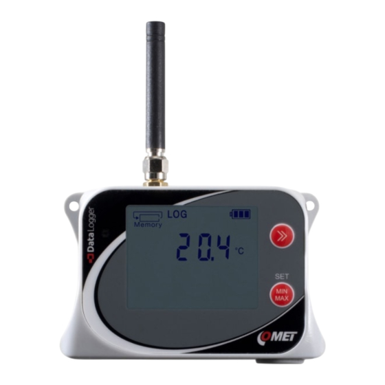
Operating the datalogger from the keypad Displaying the device data Data memory occupancy - this display section offers information about the current condition of the free space existing in the data memory. The blinking of the Memory symbol indicates that the preset memory occupancy limit has been exceeded. - Page 13 A continuous recording with a preset interval is ON and running. The recording is ON in the device and it is running at present. This kind of display is only used, when the recording activity is dependent on the alarm or the external input condition. The recording is ON in the device but it is not running at present.
- Page 14 Battery condition this symbol provides overview information about the current battery charging condition. The charging is indicated by flashing one of these symbols. Battery conditions during battery operation of the device: Fully charged battery Partly discharged battery Heavily discharged battery Totally discharged battery, the device will be switched OFF.
- Page 15 the display unit. The upper push button serves to toggle between the measured values („the screens“): The lower push button serves to toggle between the currently measured values and the Min/Max values: The device can also be set up to toggle the „screens“ automatically, in for about 5 sec interval.
-
Page 16: Menu Options
Menu Options The menu can be entered by pressing a combination of both keys. In any case, using the keypad must be enabled in the device configuration. Individual menu items, too, may be disabled in the device setup. It is e. g. possible to switch on the device in this way, but it is not possible to switch it off. -
Page 17: Models Produced
The user cannot change the measured quantities and their ranges. If wireless communication is used, it is necessary to pay attention to a sufficient level of mobile signal at the location. U0110M, U0110G One-channel thermometer This model is equipped with only one internal temperature sensor, no additional probes and sensors can be connected. - Page 18 U0141M, U0141TM, U0141G, U0141TG Four-channel thermometer U0141M for external probes U0141G These devices measure up to four temperatures from external probes of the Pt1000 series. The response to a temperature change depends on the connected probe design but it is usually many times faster than a model with an internal sensor.
- Page 19 U0843M, U0843G Two-channel binary-input thermometer for external probes This model can measure up to two temperature values, which are sensed by outdoor Pt1000/0 series probes. In addition, it is provided with two binary inputs for monitoring voltage-signal changes or changes of a signal coming from a dry contact.
- Page 20 Thermometer – hygrometer for external probe This model measures temperature, relative humidity and dew point temperature using an outdoor COMET Digi/E series probe. Its response to the temperature or relative humidity change is significantly faster than by models with internal sensor. This model is often utilized to monitor areas in which only the probe is installed, whereas the main unit is installed elsewhere.
- Page 21 U3631M, U3631G Compact thermometer - hygrometer with optional external temperature probe This model is designed to measure temperature, relative humidity and dew-point temperature by internal sensor, moreover one additional external temperature probe Pt1000/E can be connected. Internal sensors are located under the grid on the front of the device. The device also measures...
- Page 22 U4440M, U4440G Compact thermometer - hygrometer - pressure gauge - concentration meter This model is designed to measure temperature, relative humidity, dew-point temperature, barometric pressure and the concentration of CO in the air by internal sensors. Barometric pressure can be measured as absolute or recalculated to sea level.
- Page 23 U5841M, U5841G Datalogger with 3 inputs 0 – 10 V and 1 binary input This model is used to measure up to three voltage inputs 0-10 V DC while allowing one binary input to be monitored. The voltage inputs are not galvanically isolated from one another.
- Page 24 U6841M, U6841G Datalogger with 3 inputs 0 - 20 mA and 1 binary input This model is used to measure up to three signals from current loops (0 to 20) mA DC while allowing one binary input to be monitored. The current inputs are passive and are not galvanically isolated from one another.
- Page 25 U7844M, U7844G Two-channel binary-input counter This model includes four inputs. Two of them can function as counters, and all four inputs can function as binary inputs. Both counter and binary inputs serve to monitor voltage signals or signals coming from a dry contact.
- Page 26 U8410M, U8410G Compact CO concentration meter This model is designed to measure concentration of CO in the air by internal sensors. No additional probes or sensors can be connected. It is characterized by a simple and compact design and a relatively long response in the measured quantities, compare to model with external probes.
-
Page 27: Comet Vision Program
The USB-connected device is automatically detected within approx. 5 seconds (required for connection initialization time). When connected to a computer, the device is automatically added to the COMET device list. A device can be added manually after clicking on the „Add device“... -
Page 28: Setting Up The Device
Complete device setup can be performed by the aid of the COMET Vision user software (hereinafter SW). During configuration editing the device can work normally, nevertheless the access to some functions (record download, contemporary configuration editing by other users) is limited. - Page 29 General - Preferences _____________________________ In this panel you can choose the unit with which the device will measure the temperature (Default temperature unit °C/°F). With some devices the pressure unit can be chosen, too (Default atmospheric pressure unit). When the device does not measure the atmospheric pressure, but when it is necessary to know its value to measure some quantities (calculated humidity and CO ), the atmospheric pressure value must...
- Page 30 you can set the Measuring interval to 1 minute. The CO concentration channel measures with a 2-minute interval and can be extended up to 10 minutes to save more battery life. For details concerning power “Technical consumption, see parameters”. Record _________________________________________ The choices that are available in this panel serve to control the device‘s recording functions.
- Page 31 Channels_______________________________________ In this panel you can set all input channels. The assignment of the measurement value and its range to a channel is factory-set and cannot be changed. Depending on the device type, up to three calculated channels are available (for details see Annex Supply a suitable name of the location to be measured (or calculated value) for each channel and decide whether it will be switched on for...
- Page 32 lower than). Enter this limit value. In binary inputs, only the input state must be defined. Subsequently, the alarm delay time must be entered (for the duration of). This delay time serves to eliminate contingent momentary overshoots of the limit value. The hysteresis, too, has a similar significance (Alarm hysteresis).
- Page 33 An alarm can be signalized by a fast flashing of the LED diode on the device panel (Optical signalling - LED). In the case that only one alarm originating from a measurement value is active, a yellow LED is flashing. In the case that more alarms occur simultaneously, or a system alarm or an alarm originating from an exceeded memory occupancy limit...
- Page 34 - permanent - the optical and/or acoustic signalling is deactivated until new alarm occurs. In this case, the "Reactivate muted alarm signalling" item must be switched off in the device configuration. - time-limited (temporary) - if the alarm after the set time interval is still current, the optical and/or acoustic signalling is activated again.
- Page 35 set to not require the PIN code. If the PIN code is set on the SIM card and the required pin is set incorrectly in the device configuration, the SIM card will be blocked when attempting to connect to the mobile “Display operator network, see warnings”...
- Page 36 Set the interval for sending Keep-alive text messages. Such messages can be sent by the device to all selected recipients on regular interval basis. They include the datalogger identification, the current measurement values of all channels as well as the conditions of all alarms.
- Page 37 SOAP server, see chapter 8.2 Automatic data sending to the database in Comet Database manual (e.g. http://192.168.1.1/soap). To send data to the COMET Cloud storage system, select this item as the destination server and the URL will be set automatically.
-
Page 38: Application Notes
Application notes Operation with a constantly connected charger __________ Datalogger is primarily intended to be operated as an autonomous unit powered by its built-in batteries. Nevertheless, you can also operate it with a charger which is constantly connected to it, or with a computer. The datalogger’s internal charging circuitry controls the battery charging process based on its instantaneous condition, thus protecting it against damage. - Page 39 USB equipment in the computer. This may be corrected by closing the COMET Vision utility program (including the communication service) and starting it subsequently. Restart the computer, if the above mentioned measure is not the proper remedy. Check whether new HID equipment will appear in Device administrator after the device has been connected to the computer.
- Page 40 • If the blue diode does not start flashing at all, then the datalogger‘s radio section has not been activated at all. It may be caused by an improper setting: A non-functioning SIM card has been inserted, the SIM Card has been blocked because a wrong PIN has been entered, the alarm is not activated at all, no phone number is assigned to the alarm, and the like).
- Page 41 in hand, relative humidity alarm by taking the device in hand on the sensor side) and assign an SMS recipient to this alarm. • Induce an alarm condition and follow the behaviour of the blue LED diode. After turning on the modem, it should light up for a while (searching for the network), then flash more slowly (registering to the network), then quickly (sending data) and then turn off (completed).
-
Page 42: Recommendations For Operation And Maintenance
Recommendations for operation and maintenance Datalogger operation in several application areas________ Before putting the device into operation, it should be considered, if its usage is suitable for the intended purpose. In connection with this consideration the device‘s optimum settings should be determined. In the case that the device is part of a larger measurement system, instructions for its metrological and operational checks should be developed... - Page 43 Positioning of humidity sensors: The positioning of humidity sensors depends again on the application requirements. Humidity measurements in refrigerators without additional humidity stabilization can be very questionable. When the cooling is switched on/off, there may be significant changes in humidity in the range of tens of percent, even if the mean value is correct.
- Page 44 Service recommendations _________________________ Engineering support and service activities are provided by the device distributor. His contact person‘s address is given in the Certificate of warranty included with the product. WARNING - Unskilled intervention into the device may lead to loss of warranty! IE-LGR-UxxxxM-23...
-
Page 45: Technical Parameters
Technical parameters Power supply The device is supplied from an internal Li-ion battery, which is placed under the rear cover. The battery may be replaced by the producer or an authorized service provider only. Battery _________________________________________ Battery model used: Built-in Li-Ion battery A8200, 3.6V/5200mAh (included) Operating lifetime relating to a single charge of the Li-ion rechargeable battery: Several months to several years according to the device... -
Page 46: Usb Communication Interface
excessive influence of measured values. If you want to charge these devices as soon as possible, turn it off first. When the device is turned off, the fast charging mode is automatically activated. Fully charged battery is indicated on the display of the device usually within 6 hours. -
Page 47: Radio Section
Radio section The datalogger includes a radio modem intended for data transfer and sending SMS messages. This modem is only powered up and registered in the mobile operator network only when SMS messages' sending off is required. Otherwise, it is switched off. UxxxxM series - transmission power and frequency: Quad-band 850/900/1800/1900MHz GPRS Mobile Station Class B... -
Page 48: Parameters Of Datalogger Inputs
Recommended calibration interval: 2 years U0121M, U0121G ________________________________ Measured values: 2 x temperature sensed by an external COMET Pt1000/E series probe Temperature range: (-200 to +260) °C, Pt1000/3850 ppm sensor Measuring current: approx. 0.5 mA with pulses of approx. 60 ms length Input accuracy (without probes): ±0.2 °C in a range of (-200 to +100) °C... - Page 49 Recommended calibration interval: 2 years U0141M, U0141TM, U0141G, U0141TG _______________ Measured values: 4 x temperature sensed by an external COMET Pt1000/E series probe Temperature range: (-200 to +260) °C, Pt1000/3850 ppm sensor Measuring current: approx. 0.5 mA with pulses of approx.
- Page 50 U0843M, U0843G ________________________________ Measured values: 2 x temperature by an external COMET Pt1000/0 probe 2 x binary input intended for voltage to be applied to it or a dry contact (an open-collector transistor) to be connected to it. This device is not suitable for catching the „voltage applied/not applied”...
- Page 51 Response time: Is determined by the response time of the used probe (it valid if Measuring interval is set to 1 s). Resolution: 0.1 °C converter range: 16 bits Recommended calibration interval: 2 years U3120M, U3120G ________________________________ Measured values: Internal temperature, relative humidity. Dew-point temperature calculated from the internal temperature and relative humidity.
- Page 52 1 year (according to the connected probe) U3631M, U3631 _________________________________ Measured values: Internal temperature, relative humidity. 1x External temperature measured by an external COMET Pt1000/E probe. Dew-point temperature calculated from the internal temperature and relative humidity. Difference of external temperature and dew point temperature. Ranges: Internal temperature: (-20 to +60) °C...
- Page 53 - sensor accuracy ±1.8 %RH at 23 ºC in the range of (0 to 90) %RH - hysteresis < ±1 %RH - non-linearity < ±1 %RH - temperature error: see diagrams in Annex 8 Dew-point temperature: ±1.5 °C at an ambient temperature of T<...
- Page 54 U4440M, U4440G ________________________________ Measured values: Internal temperature, relative humidity, barometric pressure and the concentration of CO in the air. Dew- point temperature calculated from internal temperature and relative humidity. Ranges: Temperature: (-20 to +60) °C Relative humidity: (0 to 100) %RH without permanent (*2) condensation Barometric pressure (absolute): 700 hPa to 1100 hPa...
- Page 55 (*1) During battery charging temporary measurement inaccuracy can occur. (*2) Important information is provided in the chapter “Models produced – U4440M, U4440G” U5841M, U5841G ________________________________ Measured values: 3 x voltage (0 – 10) V 1 x binary input. This input can be configured to voltage or a dry contact (with open collector transistor acceptance).
- Page 56 U6841M, U6841G ________________________________ Measured values: 3x current input, 1 x binary input. This input can be configured to voltage or a dry contact (with open collector transistor acceptance). Unlike the U0843M (U0843G) model, this input can capture connected/disconnected voltage status. Range and input levels: Current input: Range: (0 to 20) mA DC...
- Page 57 the U0843M (U0843G) model, this input is able to catch also the „voltage applied/not applied“ states. 2 x counting input. This input, like the binary one, can be configured to voltage or dry contact (as e.g. an open- collector transistor). These counting inputs can be used as additional two binary ones.
- Page 58 Ranges: Concentration of CO in the air: 0 to 5000 ppm (it is possible to deliver the device with the range of 0 to 10000 ppm as optional) Accuracy: concentration in the air: 50 + 0.03 × MV [ppm CO at 23 °C and 1013 hPa] Temperature dependency in range -20...45 °C: typ.
-
Page 59: Operating And Storage Conditions
Operating and storage conditions Operating temperature: (-20 to +60) °C Range of the display visibility: (-10 to +60) °C Operating humidity: (0 to 95) %RH without permanent condensation for models with CO sensor (0 to 100) %RH without long-lasting condensation for other models Operating pressure: (700 to 1100) hPa for models with CO... -
Page 60: Declaration Of Conformity
Ingress protection: Protection class case with Temperature Device type electronics and rel. humidity sensor U0110M, U0110G U0121M, U0121G IP67 U0141M, U0141G U3121M, U3121G U3120M, U3120G IP67 IP30 U3631M, U3631G U4440M, U4440G IP20 IP20 U0141TM, U0141TG U0843M, U0843G U5841M, U5841G IP20... -
Page 61: Dimensions
Dimensions U0110M, U0110G U8410M, U8410G U0121M, U0121G IE-LGR-UxxxxM-23... - Page 62 U0141M, U0141G U3120M, U3120G U4440M, U4440G IE-LGR-UxxxxM-23...
- Page 63 U3121M, U3121G U3631M, U3631G IE-LGR-UxxxxM-23...
- Page 64 U0141TM, U0141TG U0843M, U0843G U5841M, U5841G U6841M, U6841G U7841M, U7841G IE-LGR-UxxxxM-23...
-
Page 65: Annexes
Annexes Annex 1: Selected error messages of the device Error Description and debugging A/D converter is at low limit, 0x0000. Error 1 Contact support. Error 2 Temperature probe is not connected, or cable is damaged. Internal converter communication error. Error 3 Contact support. -
Page 66: Annex 2: Connection Of The Pt1000/E Series Probe Connector
Error Description and debugging The source value of the calculated quantities is not available. Check in the SW whether measurement values are available Error 20 (temperature and relative humidity) for this calculated quantity in question (e.g. the dew-point temperature). Calculation failure, incorrect device calibration. Error 21 Have the device repaired. -
Page 67: Annex 3: Accuracy Of The Dew-Point Temperature Measurement
Annex 3: Accuracy of the dew-point temperature measurement Annex 4: Connecting the wires to the terminals Some inputs are equipped with a split self- locking WAGO connector block. Connect wires block with either the supplied SP013 a screwdriver corresponding the size: insert a screwdriver into the pluggable terminal block’s angular opening situated above... -
Page 68: Annex 5: Calculated Channels
(e.g. temperature, humidity, ..., according to the device type). Overview of available the Calculated channels by the device type (named as “Calculated”): Models Channel 1 Channel 2 Channel 3 Channel 4 Channel 5 Channel 6 Channel 7 U0110M U0110G U0121M T1-T2 Calculated U0121G U0141M... -
Page 69: Annex 6: Sms Message Format
Annex 6: SMS message format SMS message format for SYSTEM ALARM: The message header includes: SYSTEM ALARM<enter> „Description of the device DescDev“<enter>“ Depending on the type of alarm, the corresponding text: Data memory limit overflow, Battery warning, Battery empty, Battery Ok, External power lost, External power Ok;... - Page 70 DataKeepAliveSMS format (suitable for automated data processing): All data coded into ASCII, it means 1 Byte will be sent as 2 ASCII characters. (hex. value 0x9E will be sent as two ASCII characters ‘9’ ’E’) Initial text "Datalogger" 10 ASCII chars Space 1 ASCII char Serial number...
- Page 71 HumanKeepAliveSms format: The Text of the message is gradually consisting of the items in the order below. The length of this report is limited to max 160 characters. If the message was longer, then it sends only the first 160 characters. The format of the message: - description of the device from the configuration: max.
-
Page 72: Annex 7: Firmware Updates
Annex 7: Firmware updates FW version 0.0.130 changes - added computed channels support FW version 0.0.129 changes: - added new JSON data version format Version6 - added new parameter: TimeNow Device time at the moment of sending JSON data as count of seconds since 1.1.2000. FW version 0.0.118 changes: - added new JSON data version format Version5 - added new parameter: BatteryPercentage. -
Page 73: Annex 8: Typical Tolerance Of The % Rh Measurement
data sending occurs, logger tries to resend it twice again immediately. If it still fails, JSON message stays stored into internal buffer (if free space is available yet) and is going to be send at next sending time again. It means, unsent data packet is not lost and will be delivered later together with newer one.
Need help?
Do you have a question about the U0110G and is the answer not in the manual?
Questions and answers