Advertisement
Quick Links
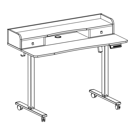
Vintage Brown / Black 2 Tier 60" x 24" Mobile Electric
Desk
Instruction Manual
SKU: DESK-E-Y60SN
Scan the QR code with your mobile device or follow the link
for helpful videos and specifications related to this product.
https://vivo-us.com/products/desk-e-y60sb
GET IN TOUCH | Monday-Friday from 7:00am-7:00pm CST
help@vivo-us.com
www.vivo-us.com
Chat live with an agent!
309-278-5303
Advertisement

Subscribe to Our Youtube Channel
Related Manuals for Vivo DESK-E-Y60SN


Summary of Contents for Vivo DESK-E-Y60SN
- Page 1 Vintage Brown / Black 2 Tier 60" x 24" Mobile Electric Desk Instruction Manual SKU: DESK-E-Y60SN Scan the QR code with your mobile device or follow the link for helpful videos and specifications related to this product. https://vivo-us.com/products/desk-e-y60sb GET IN TOUCH | Monday-Friday from 7:00am-7:00pm CST help@vivo-us.com...
-
Page 2: Electrical Safety Instructions
WARNING! If you do not understand these directions, or if you have any doubts about the safety of the installation, please call a qualified technician. Check carefully to make sure there are no missing or defective parts. Improper installation may cause damage or serious injury. Do not use this product for any purpose that is not explicitly specified in this manual and do not exceed weight capacity. -
Page 3: Tools Needed
TOOLS NEEDED DO NOT EXCEED WEIGHT CAPACITY. 176lbs Failure to do so may result in serious injury. (80kg) Level Phillips Drill Screwdriver ASSEMBLY STEPS STEP 1 Place Front Desktop (C) and Back Desktop (D) upside down on a clean flat surface. Insert Wooden Dowels (O) into the holes in both desktops and slide them together. - Page 4 STEP 2 Assemble Crossbar (H) to Leg (A) and Motorized Leg (B) using M8x50mm Screw (S-B) and 5mm Allen Wrench (T-B). STEP 3 Mount Side Brackets (E) to the frame assembly using M8x16mm Screws (S-C) and 5mm Allen Wrench (T-B).
- Page 5 STEP 4 Place the frame assembly upside down and assemble Feet (F) to Leg (A) and Motorized Leg (B) using M6x35mm Screws (S-D) and 5mm Allen Wrench (T-B). STEP 5 If desired, the foot pads on Feet (F) can be replaced with Casters (S). Unscrew the pads and thread Casters (S) onto Feet (F) using 14mm Wrench (T-A).
- Page 6 STEP 6 Place Tray (I) over Crossbar (H). STEP 7 Loosen the knobs on Sync Rod (G) using 18mm Wrench Retaining Ring (T-C) and extend the hex shaft. Insert the hex shaft into Leg (A), making sure the metal retaining ring makes contact with the leg.
- Page 7 STEP 8 Secure the frame assembly to the desktop using ST4.2x15mm Screws (S-A) and a Phillips screwdriver. STEP 9 Assemble Control Panel (K) to Front Desktop (C) using ST4.2x15mm Screws (S-A) and a Phillips screwdriver.
- Page 8 STEP 10 Plug the cable from Motorized Leg (B) into Control Panel (K). Connect Control Panel (K) and Power Cable (L) to AC Adapter (J). STEP 11 Insert AC Adapter (J) into Tray (I).
- Page 9 STEP 12 Remove adhesive backing from Cable Clips (Q). Stick them to the underside of the desktop assembly, and manage cables. STEP 13 Insert Cable Management Cover (P) into Back Desktop (D). STEP 14 Assemble Shelf Braces (X) to Back Desktop (D) using Wooden Dowels (O) and ST4.2x40mm Screws (S-E).
- Page 10 STEP 15 Insert Cam Lock Screws (S-F) into Lower Shelf Panel (T). STEP 16 Assemble Lower Shelf Panel (T) to Shelf Braces (X) using Wooden Dowels (O) and Cam Lock Screws (S-F). STEP 17 Insert Cam Locks (S-G) into the center hole in Shelf Braces (X).
- Page 11 STEP 18 Assemble Right Shelf Panel (V) and Left Shelf Panel (W) to Lower Shelf Panel (T) using Wooden Dowels (O). STEP 19 Secure the shelf assembly to Back Desktop (D) using ST4.2x40mm Screws (S-E).
- Page 12 STEP 20 Insert Cam Lock Screws (S-F) into Back Shelf Panel (U). STEP 21 Assemble Back Shelf Panel (U) to the shelf assembly using Wooden Dowels (O).
- Page 13 STEP 22 Insert Cam Locks (S-G) into the rear holes of Right Shelf Panel (V), Left Shelf Panel (W), and Shelf Braces (X). STEP 23 Secure Back Shelf Panel (U) to Back Desktop (D) using ST4.2x40mm Screws (S-E).
- Page 14 STEP 24 Unfold Drawers (R) and place the drawer insert inside. STEP 25 Insert Drawers (R) into the drawer assembly.
- Page 15 STEP 26 Plug Power Cable (L) into an AC power outlet. The desk is now ready for use. Please refer to the Control Panel User Guide for operational instructions. CAUTION! Do not exceed desk Keep area of vertical Keep weight on desk Leave enough slack in weight limit.
- Page 16 AVG. RESPONSE TIME (within office hrs) - 23% within < 15m - 38% within < 30m - 61% within < 1hr - 83% within < 2hr - 92% within < 3hr FOR MORE VIVO PRODUCTS, CHECK OUT OUR WEBSITE AT: www.vivo-us.com...
Need help?
Do you have a question about the DESK-E-Y60SN and is the answer not in the manual?
Questions and answers