Table of Contents
Advertisement
Quick Links
20____
Year of Manufacture:
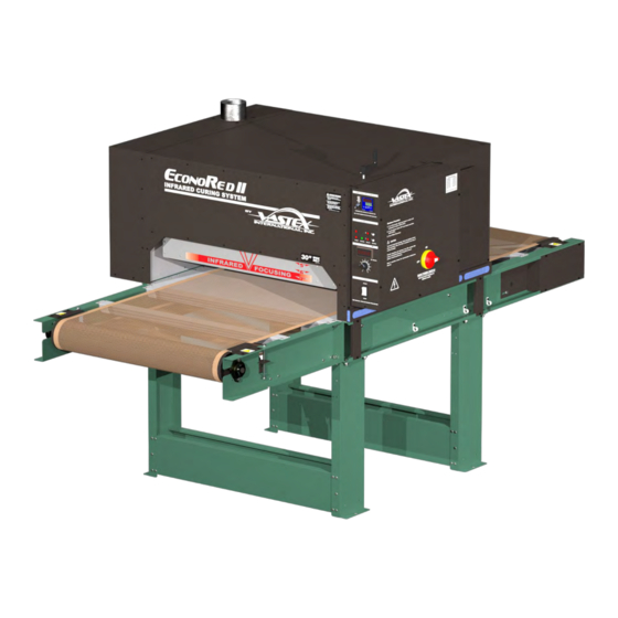
EconoRed-II-Series Dryers
Assembly, Operating, and Maintenance Instructions for all
•
•
•
•
•
•
•
•
•
Electrical Drawing #:
Serial Number:
VTX
(Please log your machine's serial number and date of purchase for future reference.)
EC-II-30 and EC-II-54 Dryers
Pg #
2-3
4-6
7
8-10
11-12
13
14-15
16
17
Rev:______
/
Date:____
____
(EC-II-30 Shown)
Vastex International, Inc.
7 Emery Street
Bethlehem, PA
Phone# 610 625-2702 Fax# 610 625-2775
Web Site www.vastex.com
Authorized Representative in Europe:
Certification Experts BV
Nieuwstad 100 1381 CE Weesp,
The Netherlands
Tel : + 31 (0) 294 - 48 33 55
Fax : + 31 (0) 294 - 41 46 87
Vastex E-mail assistance
Purchasing & Product Info:
sales@vastex.com
Electrical Support:
stech@vastex.com
Tech Support, Mechanical Setup, and Operation:
techsupport@vastex.com
/
______
Screen Printing Issues & Support:
printech@vastex.com
Doc. # 01-15-010M
Original Instructions
Advertisement
Table of Contents

Related Manuals for VASTEX EconoRed-II Series


Summary of Contents for VASTEX EconoRed-II Series
-
Page 1: Table Of Contents
Doc. # 01-15-010M Original Instructions EconoRed-II-Series Dryers Assembly, Operating, and Maintenance Instructions for all EC-II-30 and EC-II-54 Dryers (EC-II-30 Shown) Pg # Vastex International, Inc. 7 Emery Street • Introduction / Safety Bethlehem, PA Phone# 610 625-2702 Fax# 610 625-2775 •... -
Page 2: Introduction / Safety
Your Vastex Infrared Dryer has been Factory tested and burned in for a period of 2-8 hours. All components are tested to be sure they work correctly when the Dryer leaves our factory. - Page 3 Safety, continued Stability during use, transportation, assembly, dismantling when out of service, testing, and foresee- • able breakdowns: This equipment is designed and expected to be stable during all foreseeable conditions, so long as the procedures and instructions given in this manual are followed. Safe handling, transport, and storage: Before storing the unit, follow the shutdown procedure on Pg.11 •...
-
Page 4: Assembly
Assembly Tools Needed: (1) Crowbar or Claw Hammer, (2) 9/16” open end wrenches, (1) 7/16” open end wrench or socket, (1) 1/4” nut driver or flat blade screw driver 1) Dismantle the crate that your dryer came in. Remove the top and sides with a crowbar or claw hammer. Conveyor 2) Remove the front and rear conveyor sections and Side... - Page 5 Proper venting is important.) 9) Have a licensed electrician complete the electrical hook-up and fill out the warranty card. Send it back to Vastex to validate your warranty. A wiring diagram has been included with this manual. One is also adhered to the inside of the control box cover.
- Page 6 Assembly (cont’d) 10) Plug the wire from the conveyor motor into the rear of the control box. 11) Turn on the system switch and then the belt speed control. See Dryer Operation– Startup Procedure. Check that the belt is moving and running in the center of both pulleys. If belt is tracking in the center of the pulley, dryer is ready for use.
-
Page 7: Hd Drive
Optional HD Drive Features: Drive Roller Tensioner • H.D. Gear motor 1/4 HP, Pt.# 04-02-047 (connected to #1 chamber belt speed controller) • CONVEYOR BELT PATH TOP OF BELT BELT RETURN DRIVE ROLLER TENSIONER Drive Roller Tensioner 4” 4” Drive End LH Side Bottom View Conveyor Drive End Drive End RH Side After conveyor belt is installed, adjust Drive Roller Tensioner... -
Page 8: Component Identification
The belt does not have to be perfectly centered on the pulley but should not be hanging over either edge. Pulley The pulleys at either end of the conveyor are made by VASTEX of 4 ½ inch steel tubing with ¾ inch center shaft. They are mounted on self aligning flange bearing blocks for precision rolling. - Page 9 Controls Heat Switch: Controls power to heater only. Temperature Control: Set and control temperature here. See Page 14 for Controller information. Control Output Light: A 250 volt GREEN pilot light is wired to the output side of the temperature controller. This light should cycle on & off with the controller. It verifies that the controller output voltage is going to the relay coil.
- Page 10 Controls (cont’d) Reversing Switch: Used to reverse the direction of belt travel. (optional) Main Power Switch: Disconnects ALL power to the internal components (Disconnect Switch) to allow safe access to the inside of the control box. Power Lights are wired to the output side of the Disconnect Switch, meaning it is only safe to enter the control box when the Power lights are NOT illuminated.
-
Page 11: Operation
Dryer Operation Control System Summary: The control system in your dryer is called a “closed loop system”. The system includes a Digital Controller mounted to the control panel, a Sensor mounted in a shield under the heater, a relay and an Infrared Heater. The digital controller is set to the desired temperature and the Sensor measures the temperature at the face of the heater. - Page 12 Dryer Operation Cont’d Volts Vs Time in Heat Single Chamber EC-II Time Through Chamber Volts Time Through Chamber Volts The chart at the right is based on... 11 Sec 130 V 37 sec 40 V • A 36” Single Chamber heat zone. 13 Sec 115 V 43 Sec...
-
Page 13: Maintenance
Maintenance Caution! Power must be turned off at the external disconnect before entering any part of this machine. The red Power Light labeled “Power” must be off!! A qualified electrician should perform any internal testing requiring power on! Electrical Electrical connections will loosen in time from heating and cooling. Every three (3) months the power should be turned Connections off at the external disconnect, or unplugged, and all the points of connection should be inspected and tightened. -
Page 14: Troubleshooting
80% of time and off 20%). Controller can remain in this mode while resuming production. Celsius / The temperature controller on your Vastex Infrared dryer is normally set to Fahrenheit as a default. Follow the procedure below to Fahrenheit switch the controller from Fahrenheit to Celsius. - Page 15 Check for burned out heater • No Heat & power light is on System fuses on control panel • Note operation of pilot lights, Call Vastex • Note operation of pilot lights Heat too high (Relay can stick on or off) •...
-
Page 16: Dryer & Exhaust Hood Ducting
Pg. 16... -
Page 17: Warranty / Terms & Conditions
The defective part or parts will be repaired or replaced at the discretion of Vastex International, Inc. If the equipment in question is less than one (1) year old, it will be shipped to the customer at no charge, with an RGA issued by Vastex for the defective part. The defective part must be shipped back to Vastex freight prepaid within 30 days or the account will be billed. - Page 18 Pg. 18...
- Page 19 Pg. 19...
- Page 20 Pg. 20...
Need help?
Do you have a question about the EconoRed-II Series and is the answer not in the manual?
Questions and answers