Advertisement
20____
Year of Manufacture:
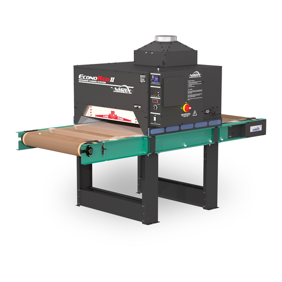
EconoRed (ER) Series Dryers
Assembly, Operating, and Maintenance Instructions for
ER-II-30, ER-II-54, ER-III-30, & ER-III-54 Dryers
Introduction / Safety
SHD Drive
Warranty / Terms & Conditions
Electrical Drawing #:
Serial Number:
VTX
(Please log your machine's serial number and date of purchase for future reference.)
Pg #
2-3
4-8
9
10
11
12-13
14-15
16
17
18-19
20
Rev:______
/
/
Date:____
____
______
Original Instructions
(EC-II-30 Shown)
Vastex International, Inc.
7 Emery Street
Bethlehem, PA
Phone# 610 625-2702 Fax# 610 625-2775
Web Site www.vastex.com
Authorized Representative in Europe:
Certification Experts BV
Nieuwstad 100 1381 CE Weesp,
The Netherlands
Tel : + 31 (0) 294 - 48 33 55
Fax : + 31 (0) 294 - 41 46 87
Vastex E-mail assistance
Purchasing & Product Info:
sales@vastex.com
Electrical Support:
stech@vastex.com
Tech Support, Mechanical Setup, and Operation:
techsupport@vastex.com
Screen Printing Issues & Support:
printech@vastex.com
Doc. # 01-32-001A
Advertisement

Related Manuals for VASTEX EconoRed Series


Summary of Contents for VASTEX EconoRed Series
-
Page 1: Table Of Contents
EconoRed (ER) Series Dryers Assembly, Operating, and Maintenance Instructions for ER-II-30, ER-II-54, ER-III-30, & ER-III-54 Dryers Pg # (EC-II-30 Shown) Introduction / Safety Vastex International, Inc. Assembly 7 Emery Street Bethlehem, PA SHD Drive Phone# 610 625-2702 Fax# 610 625-2775 ... - Page 2 Your Vastex Infrared Dryer has been Factory tested and burned in for a period of 2-8 hours. All components are tested to be sure they work correctly when the Dryer leaves our factory.
- Page 3 In case an abnormal symptom occurs, for example excessive vibration, noise, and strong smell or smoke develop- ment, turn off the VASTEX Conveyor Curing System and contact a qualified technician. Immediately turn off the VASTEX Conveyor Curing System if products become jammed in the drying chamber or conveyor belt. ...
- Page 4 Assembly (1of5) Tools Needed: (1) Crowbar or Claw Hammer, (2) 9/16” open end wrenches, (1) 7/16” open end wrench or socket, (1) 1/4” nut driver or flat blade screw driver, (1) 1/8” allen wrench Econored-II-54 shown for illustration purposes. Econored II and III are assembled and operated in the same manner.
- Page 5 Assembly (2of5) Conveyor Side 3) Carefully slide the dryer and conveyor assembly off the pallet and onto the shop floor. Lift from Conveyor Sides only. Do not lift from Conveyor Bed! Conveyor Side DO NOT LIFT FROM CONVEYOR BED Caution! The heating chamber sits on top of the conveyor pins.
- Page 6 Assembly (3of5) Ducting 5) Install Dryer ducting. CFM cannot be reduced by more than 10% at exit of ducting. An exhaust booster must be used if CFM is reduced more than 10% due to length of duct or amount of bends. Please seek professional ad- vice if this is not your area of expertise.
-
Page 7: Assembly
(4of5) Electrical 7) Have a licensed electrician complete the electrical hook-up and fill out the warranty card. Send it back to Vastex to validate your warranty. A wiring diagram has been included with this manual, and is also adhered to the inside of the control box cover. - Page 8 Assembly (5of5) Set Screw Crank Handle Allen Wrench 9) Install the crank handle onto the shaft on top of the chamber. Align set screw to the flat on shaft and tighten with 1/8” allen wrench. Raise heaters to full up position. Flat 10) The belt needs to be installed as shown in the diagram below.
- Page 9 Optional Drive Idler Features: Drive Idler Provides additional grip on rear pulley. Required on machines over 17’(5m) in length CONVEYOR BELT PATH Belt TOP OF BELT BELT RETURN Aligner Drive Idler Conveyor Brace (Route Belt over top of Braces) Drive Idler on 17’+ DRIVE ROLLER TENSIONER Long Conveyor...
-
Page 10: Belt Tracking
Belt Tracking Aligner bolt Belt Tracking Belt aligner pulley (Move in small increments while belt is moving. Do not leave conveyor running unattended.) If the belt is slipping, add belt tension by raising equally both sides of aligner roller. 1”-2” of belt sag at the bottom side is desirable. -
Page 11: Component Identification
The belt does not have to be perfectly centered on the pulley but should not be hanging over either edge. Pulley The pulleys at either end of the conveyor are made by VASTEX of 4 ½ inch steel tubing with ¾ inch center shaft. They are mounted on self aligning flange bearing blocks for precision rolling. - Page 12 Controls (1of2) Temperature Control: Set and control temperature here. See Page 14 for Controller information. Heat Switch: Controls power to heater only. Relay Output Light: This 250 volt RED pilot light is wired to the output side of the relay. This light will cycle on &...
-
Page 13: Controls
Controls (2of2) CPC Connector (Motor) Incoming Power Main Power Switch: Disconnects ALL power to the internal components (Disconnect Switch) to allow safe access to the inside of the control box. Power Lights are wired to the output side of the Disconnect Switch, meaning it is only safe to enter the control box when the Power lights are NOT illuminated. - Page 14 Dryer Operation (1of2) Control System Summary: The control system in your dryer is called a “closed loop system”. The system includes a Digital Controller mounted to the control panel, a Sensor mounted in a shield under the heater, a relay and an Infrared Heater. The digital controller is set to the desired temperature and the Sensor measures the temperature at the face of the heater.
-
Page 15: Operation
Time through chamber As explained on the Controls page, your Vastex dryer displays Voltage sent to the motor in reference to Conveyor speed. Below you will find an example chart relating Voltage to Time Through Chamber. Time Through Chamber is the time it takes an object to travel from the beginning to the end of the Heat Chamber. -
Page 16: Maintenance
Maintenance Caution! Power must be turned off at the external disconnect, or the machine unplugged, before entering any part of this machine. The red Power Light labeled “Power” must be off!! A qualified electrician should perform any internal testing requiring power on! Maintenance Schedule WEEKLY MONTHLY... -
Page 17: Drive Chain Adjustment
Drive Chain Adjustment (Standard) 1) To remove the chain guard, unfasten the four Screws black sheet metal screws. Be sure to replace the guard after adjustment is made. Chain Guard Do not operate with Chain Guard removed. Serious View with chain guard removed Injury may result! Pulley Sprocket (w/ 2 set screws) -
Page 18: Troubleshooting
Troubleshooting (1of2) Caution! Power must be turned off at the external disconnect, or the machine unplugged, before entering any part of this machine. The red Power Light labeled “Power” must be off!! A qualified electrician should perform any internal testing requiring power on! Belt Speed Min/Max Adjustment Setting the low speed pot adjustment: The low speed pot should be set so the belt (or sprocket) moves very slow at the lowest setting on the controller,... - Page 19 3) After releasing the button, the work FILE will be displayed. Press the scroll button one time and the word will disappear. Celsius / The temperature controller on your Vastex Infrared dryer is normally set to Fahrenheit as a default. Follow the procedure below to Fahrenheit switch the controller from Fahrenheit to Celsius.
- Page 20 The defective part or parts will be repaired or replaced at the discretion of Vastex International, Inc. If the equipment in question is less than one (1) year old, it will be shipped to the customer at no charge, with an RGA issued by Vastex for the defective part. The defective part must be shipped back to Vastex freight prepaid within 30 days or the account will be billed.
Need help?
Do you have a question about the EconoRed Series and is the answer not in the manual?
Questions and answers