
Related Manuals for Super Systems H2-SGA


Summary of Contents for Super Systems H2-SGA
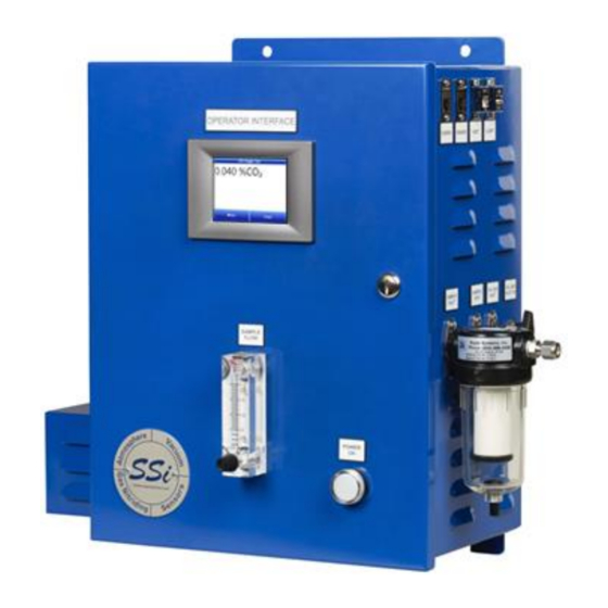
- Page 1 Single Gas Analyzer For CO, CO , or CH OPERATIONS MANUAL Super Systems Inc. 7205 Edington Drive Cincinnati, OH 45249 513-772-0060 Fax: 513-772-9466 www.supersystems.com...
- Page 2 C.P. 76120 Queretaro, Qro. 200336 Phone: +52 442 210 2459 Phone: +86 21 5206 5701/2 http://www.supersystems.com.mx http://www.supersystems.cn Super Systems India Pvt. Ltd. A-26 Mezzanine Floor, FIEE Complex, Okhla Indl. Area, Phase – 2 New Delhi, India 110 020 Phone: +91 11 41050097 http://www.supersystemsindia.com Super Systems Inc.
-
Page 3: Table Of Contents
Span Calibration Procedure ....................19 Digital IO Card (Menu Option) .....................20 Passcodes (Menu Option) ......................20 Control Interface via Web Browser ....................21 Main ............................21 Instrument Information ......................22 Sensor Information ........................23 Instrument Configuration ......................24 Output Configuration ........................25 Super Systems Inc. Page 3 of 37... - Page 4 Single Gas Analyzer (SGA) Operations Manual Output Calibration ........................26 Sensor Calibration ........................27 Alarms ............................28 SSI Configuration ........................29 Read/Write Registers .........................30 Network Configuration .......................31 Replacement Parts ........................32 Warranty............................33 Revision History ..........................34 Super Systems Inc. Page 4 of 37...
-
Page 5: Introduction
122 °F (50 °C) Analog Outputs 2 (4-20mA or 0-5 V) Serial Communications 2 RS485 ports using Modbus RTU, configurable baud rate Ethernet 1 port 1 Type A port, 1 Type B port Super Systems Inc. Page 5 of 37... -
Page 6: Mechanical Diagrams
Single Gas Analyzer (SGA) Operations Manual Mechanical Diagrams Super Systems Inc. Page 6 of 37... -
Page 7: Initial Network Configuration
The Read/Write Registers page gives access to the underlying Modbus registers of the SGA. This page is primarily intended for testing and troubleshooting purposes. Please contact SSi before attempting to make any changes to the settings on this page. Super Systems Inc. Page 7 of 37... -
Page 8: Nlocateip Method
IP address that you will want to use. Once you have found the IP address, you should be able to complete any additional network configuration using the web interface. See the Super Systems Inc. Page 8 of 37... - Page 9 The Read/Write Registers page gives access to the underlying Modbus registers of the SGA. This page is primarily intended for testing and troubleshooting purposes. Please contact SSi before attempting to make any changes to the settings on this page. Super Systems Inc. Page 9 of 37...
-
Page 10: Touch Screen Interface
If needed, call SSi at (513) 772-0060. Touch Screen Interface Main Screen The Main screen shows the current percentage of CO . From here the user can enter the Menu screen or the Chart screen. Menu Screen Super Systems Inc. Page 10 of 37... -
Page 11: Trend Chart
- will allow the user to select or de-select the trend lines on the trend chart to display. If the checkbox next to each trend line is checked, then that trend line will be displayed. Super Systems Inc. Page 11 of 37... - Page 12 The left-pointing green arrow button - - will move the chart’s view backward in time by the specified chart interval. The chart interval button - - will determine the number of hours displayed on the trend chart. Super Systems Inc. Page 12 of 37...
-
Page 13: Chart Sub Menu
ID or initials and a note. The user has the option to enter a note using the operator interface keyboard, where he or she will be able to type in the note; or the user can use the Signature mode, which will allow them to write a note using a stylus. Super Systems Inc. Page 13 of 37... -
Page 14: Instrument Information (Menu Option)
Instrument Information (Menu Option) The Instrument Information screen provides basic information about the unit, including Desciption, Part #, Serial #, Sub Serial #, Main Version #, and Sensor Version #. Pump Control (Menu Option) Super Systems Inc. Page 14 of 37... -
Page 15: Exit Program (Menu Option)
“Off,” and tap “Select.” To exit the screen without changing the pump status, tap “Cancel.” Exit Program (Menu Option) The Exit Program option allows the user to shut down the SGA touchscreen, after a confirmation dialog box is displayed. Instrument Configuration (Menu Option) Super Systems Inc. Page 15 of 37... -
Page 16: Output Configuration (Menu Option)
Output Configuration (Menu Option) The SGA has two outputs. These can be configured for Source, Zero Value, Span Value, Range, and Manual. The Source is the gas that applies to that output (NDIR Gas or External). Super Systems Inc. Page 16 of 37... -
Page 17: Communications (Menu Option)
The Communications menu allows the user to set the IP Address, Subnet Mask, and Gateway for the SGA. To change these values, tap the desired row, then tap “Edit.” Enter the new value Super Systems Inc. Page 17 of 37... -
Page 18: Alarms Setup
Do not change these values without consulting your IT professional. Doing so could cause IP conflicts and other network issues. Alarms Setup The Alarms option allows you to set lower and upper limits and assign actions to readings for the SGA. Super Systems Inc. Page 18 of 37... -
Page 19: Output Calibration (Menu Option)
“AL2” will energize Relay 4; “Both” will energize Relays 3 and 4. Output Calibration (Menu Option) Overview The Output Calibration screen allows the user to perform a zero/span calibration on the analog outputs. Super Systems Inc. Page 19 of 37... -
Page 20: Zero Calibration
4. Tap “Measured value (mA)” and tap the “Edit mA” button. 5. Enter the measured value and tap “OK.” 6. Then, tap “Run Cal” and tap the “Run Cal” button. Sensor Calibration (Menu Option) Super Systems Inc. Page 20 of 37... -
Page 21: Overview
It is good practice to begin the flow of gas before attaching the calibration gas to the instrument. This will prevent any high pressure bursts from entering the instrument. Calibration gases can be obtained from Super Systems, however they can also be obtained from any supplier of custom gases. -
Page 22: Span Calibration Procedure
5. At this point, tap to highlight “Run Calibration” and tap the “Run Calibration” button. 6. The Calibration Timer on the screen will count down, and when it reaches zero the Current gas value will adjust to match the Gas concentration. Digital IO Card (Menu Option) Super Systems Inc. Page 22 of 37... -
Page 23: Passcodes (Menu Option)
The Passcodes menu allows the user to set Supervisor and Administrator Passcodes. To change the passcodes, tap to highlight the desired access level, then tap “Set Passcode.” Enter the new passcode on the ensuing screen and tap “OK.” Control Interface via Web Browser Super Systems Inc. Page 23 of 37... -
Page 24: Main
The main page displays the percentage composition of the gas for which the SGA is configured. In the example below, the percentage composition of the gas is displayed. Figure 3 - Main Page (with CO Percentage Shown) Instrument Information Super Systems Inc. Page 24 of 37... -
Page 25: Sensor Information
This information can be useful for troubleshooting purposes. Figure 4 - Instrument Information Page Sensor Information Super Systems Inc. Page 25 of 37... -
Page 26: Instrument Configuration
These figures are a snapshot of the live data when this calibration was performed. Note that this is for diagnostic use only. Call SSi at (513) 772-0060 with questions. Figure 5 - Sensor Information Page Instrument Configuration Super Systems Inc. Page 26 of 37... -
Page 27: Output Configuration
Web Access Code: Enter the desired login code for accessing the website and click “Set Code” to save. Min %CO2: This Value is set in the factory; do not change without contacting SSi. Figure 6 - Instrument Configuration Page Output Configuration Super Systems Inc. Page 27 of 37... - Page 28 Manual (%): A %Output entered manually. Use the applicable “Set” button to set each parameter (for example, use “Set Source” to set the source). Figure 7 - Output Configuration Page Output Calibration Super Systems Inc. Page 28 of 37...
- Page 29 4. With a multimeter, measure the mA value at the output. Enter that value in the “Entered Measured value” field and press “Calibrate”. 5. Repeat the process above for the appropriate Span Output. Figure 8 - Output Calibration Page Sensor Calibration Super Systems Inc. Page 29 of 37...
-
Page 30: Alarms
“Enter gas concentration” field. 8. Press “Calibrate”. A Calibration Timer will count down. 9. Once the Calibration Timer has counted down, the span value will be calibrated. Figure 9 - Sensor Calibration Page Alarms Super Systems Inc. Page 30 of 37... -
Page 31: Ssi Configuration
There are four possible actions for the alarms: “None” will not energize any relays. “AL1” will energize Relay 3; “AL2” will energize Relay 4; “Both” will energize Relays 3 and 4. SSI Configuration Super Systems Inc. Page 31 of 37... -
Page 32: Read/Write Registers
The “Set Val” button, when pressed, will commit the entered value to the specified register location. Figure 10 - SSI Configuration Page Read/Write Registers Super Systems Inc. Page 32 of 37... -
Page 33: Network Configuration
The Read/Write Registers page gives access to the underlying Modbus registers of the SGA. This page is primarily intended for testing and troubleshooting purposes. Please contact SSi before attempting to make any changes to the settings on this page. Network Configuration Super Systems Inc. Page 33 of 37... -
Page 34: Replacement Parts
If Enable DHCP is not checked, IP and other settings can be changed manually. These settings should be verified with your network administrator before being changed. Failure to do so could result in IP conflicts and other network issues. Replacement Parts Super Systems Inc. Page 34 of 37... - Page 35 Terminal Block, Pluggable 6-Position 33305 Terminal Block, Pluggable 4-Position, Vertical 33353 Terminal Block, Pluggable 3-Position 33310 Sensors Hydrogen Sensor, In-Situ A20829 Oxygen Sensor, 4-Wire Analog 31435 CO Sensor 13672-CO Sensor 13672-CO2 Sensor 13672-CH4 Super Systems Inc. Page 35 of 37...
-
Page 36: Warranty
Warranty Limited Warranty for Super Systems Products: The Limited Warranty applies to new Super Systems Inc. (SSI) products purchased direct from SSI or from an authorized SSI dealer by the original purchaser for normal use. SSI warrants that a covered product is free from defects in materials and workmanship, with the exceptions stated below. -
Page 37: Revision History
Single Gas Analyzer (SGA) Operations Manual Revision History Rev. Description Date MCO # First release 7/11/2023 2338 Super Systems Inc. Page 37 of 37...
Need help?
Do you have a question about the H2-SGA and is the answer not in the manual?
Questions and answers