Table of Contents
Advertisement
Quick Links
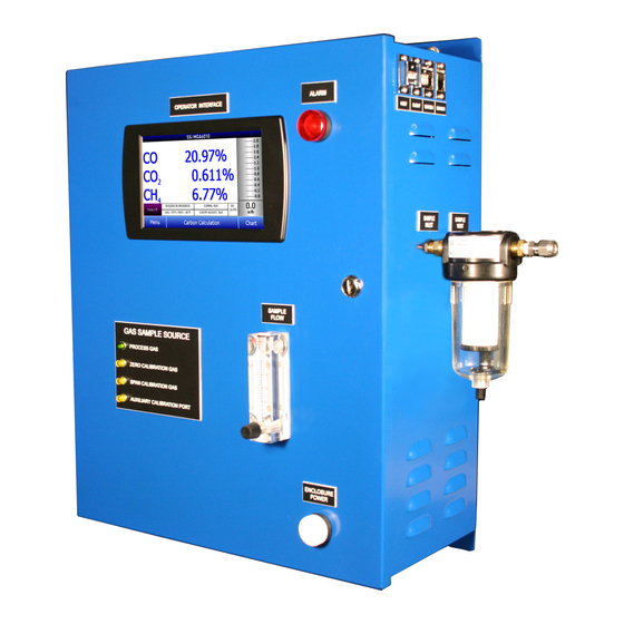
MGA 6010
Multi-Gas IR Analyzer
(CO, CO
, and CH
Gas Analyzer
2
4
with Optional H
Measurement and
2
% Carbon, % Dissociated Ammonia, % NH
, K
, and
3
N
K
Calculation Capabilities)
C
Operations Manual
Please read, understand, and follow these instructions before operating this equipment.
Super Systems, Inc. is not responsible for damages incurred due to a failure to comply with these
instructions. If at any time there are questions regarding the proper use of this analyzer, please contact
us at 513-772-0060 for assistance.
Advertisement
Table of Contents

Related Manuals for Super Systems MGA 6010


Summary of Contents for Super Systems MGA 6010
- Page 1 Please read, understand, and follow these instructions before operating this equipment. Super Systems, Inc. is not responsible for damages incurred due to a failure to comply with these instructions. If at any time there are questions regarding the proper use of this analyzer, please contact...
- Page 2 MGA 6010 Operations Manual Super Systems Inc. USA Office Super Systems Europe Corporate Headquarters: Unit E, Tyburn Trading Estate, 7205 Edington Drive Ashold Farm Road, Birmingham Shipping Address: B24 9QG 7245 Edington Drive UNITED KINGDOM Cincinnati, OH 45249 Phone: +44 (0) 121 306 5180 Phone: (513) 772-0060 http://www.supersystemseurope.com...
-
Page 3: Table Of Contents
MGA 6010 Operations Manual Table of Contents Introduction ..............................5 Specifications ..............................6 Unpacking the Device ............................ 7 Mechanical Installation ..........................7 Enclosure Mounting ............................7 Wiring Connections ............................8 Plumbing Connections ............................ 9 Basic Operating Description ........................11 Default Screen ............................11 Pump Operation ............................ - Page 4 MGA 6010 Operations Manual Revision History ............................45 Appendix A: Piping Diagram ........................46 Appendix B: Digital Inputs on the MGA 6010 ....................47 Appendix C: Modbus Registers ........................48 Appendix D: Configuration Parameters ...................... 66 Super Systems Inc. Page 4 of 67...
-
Page 5: Introduction
MGA 6010 Operations Manual Introduction The Model MGA 6010 (see part numbers in the Parts List on page 42) is a Multi-Gas IR analyzer. It measures Carbon Monoxide (CO), Carbon Dioxide (CO ) and Natural Gas (CH ) typically found in an endothermic atmosphere. -
Page 6: Specifications
MGA 6010 Operations Manual Specifications The unit is designed and manufactured for the atmosphere heat treating industry; however, its uses go beyond the scope of these applications. Range: 0 – 30% of gas concentration. Accuracy: +/-1% of full scale (+/-0.3% of gas concentration, based on 30%). -
Page 7: Unpacking The Device
Enclosure Mounting It is recommended that the MGA 6010 be mounted as close to the sampling point as possible, since that will reduce the length of the plumbing lines that will need to be maintained. It is intended for use in a heat treating environment, but care should be taken not to mount it too close to a furnace or other heat source. -
Page 8: Wiring Connections
The right side of the enclosure also contains two Ethernet ports, one USB A port and one USB B port. These can be used to communicate to the MGA 6010. For detailed information on the use of these ports, please see the section of this manual, Communications and Source Setup. -
Page 9: Plumbing Connections
If calibrations are being performed manually, this port should be used for both gases. The flow of gas through the MGA 6010 is controlled by solenoid valves. Each valve is normally closed, and for safety purposes all valves will shut to prevent unwanted furnace gases from entering the instrument when power to the enclosure is lost or the specified sampling parameters are not met. - Page 10 MGA 6010 Operations Manual Super Systems Inc. Page 10 of 67...
-
Page 11: Basic Operating Description
After the power switch is turned on, it will take approximately 30 seconds for the MGA 6010 software to automatically load. Once the software is properly loaded, the instrument is ready to use. Power to the MGA can be turned off by tripping the circuit breaker inside the enclosure. -
Page 12: Pump Operation
Automatic and Off. Carbon Calculation The MGA 6010 determines the percent carbon in the sample gas using measured amounts of CO, CO , and along with the Furnace Temperature. The Furnace Temperature is either entered by the user or obtained automatically from the Furnace Temperature Controller via RS-485 communications. -
Page 13: Chart
MGA 6010 Operations Manual Using infra-red analysis is considered a more accurate method for determining the percent carbon of a gas compared to using an oxygen probe alone. The single point oxygen probe assumes a theoretical mixture of endothermic gas to infer the percent carbon whereas the gas analyzer will measure the exact composition of the process gas. -
Page 14: Chart Sub Menu
MGA 6010 Operations Manual The right-pointing arrow with the vertical line next to it button - - will toggle between viewing the chart in or out of real-time. When in real-time mode, the chart will automatically be updated once a minute. -
Page 15: Menu Lists
MGA 6010 Operations Manual Pressing the red ‘X’ in the top right-hand corner of the screen will take the user back to the status screen. Menu Lists Accessing the menu screen will show three or four available options, depending on whether the Nitrider Calculation feature is installed. -
Page 16: Carbon Calculation
MGA 6010 Operations Manual To see the full range of options available, the user must use the Configuration Pass Code (Default = 2). This provides the user with all available options including calibration and setup functions. To access any items on the menu list, touch the item to highlight it and then press Detail. A specific description of each item on the list follows. -
Page 17: Nitrider Calculation (Available On Units Configured For Nitriding & Fnc Applications)
(K ). To access these values, open the Nitrider Calculation page. NOTE: If the MGA 6010 unit you are using does not have the Nitrider Calculation option, and you would like this feature added, please contact SSi at 513-772-0060. -
Page 18: Sessions
CO , CO, and H 0. The MGA 6010 performs the required calculation using user-provided flow values and displays the calculated K value on the Nitrider Calculation page. - Page 19 MGA 6010 Operations Manual This screen will identify sessions within the date range specified at the top of the screen. As a default, sessions from the past 24 hours are shown. By expanding the data range, additional sessions can be seen.
-
Page 20: Pump Control
(in seconds) to delay turning the pump on (Pump On Delay) and off (Pump Off Delay). Sensor Calibration On the MGA 6010, you can perform a sensor calibration with one of four calibration sources. These sources are displayed when Sensor Calibration is first selected: Automatic Calibration Port, Auxiliary Calibration Port, Sample Line (with pump on), and Sample Line (with pump off). - Page 21 MGA 6010 Operations Manual Gas Inlet Ports for Automatic Calibration The Auxiliary Calibration Port makes use of the Auxiliary Calibration Gas Inlet, located on the side of the unit and in the middle of the gas inlets for Zero Calibration and Span Calibration. A single gas line is run to the Auxiliary Calibration Gas Inlet port for zero and span calibration.
- Page 22 MGA 6010 Operations Manual Sample Inlet Port Used for Sample Line Calibration Once you have attached the gas line as needed and selected the desired calibration source, tap OK. A screen similar to the one shown below will be displayed.
-
Page 23: Performing A Zero Calibration
It is good practice to begin the flow of gas before attaching the calibration gas to the instrument. This will prevent any high pressure bursts from entering the instrument. Calibration gases can be obtained from Super Systems, however they can also be obtained from any supplier of custom gases. -
Page 24: Performing A Span Calibration
“Communications and Source Setup – Atmosphere/ Temp Sources.” The Automatic Sampling Parameters screen will allow the user to adjust the way that the MGA 6010 updates the COF / PF in the atmosphere controller. All of the parameters on this page can be disregarded if the “COF/PF Adjustment Mode”... -
Page 25: Cof/Pf Adjustment Interval (Minutes)
Minimum Millivolt condition (0 = disabled) This determines the behavior of the MGA 6010 when the minimum millivolts value is reached. Two settings are available: ... -
Page 26: Communications And Source Setup
Manually Setting the IP Address 1. Log in to the MGA 6010 touch screen using the supervisor access code (by default, this code is ‘2’). 2. Access the Instrument Setup → General Setup menu. 3. Select “Shut Down Software” followed by “Yes”. -
Page 27: Atmosphere/Temp Sources
MGA 6010 Operations Manual Atmosphere/Temp Sources RS485 communications can be set up to automatically enter and update data from the oxygen probe and, if desired, make modifications to the COF/PF in the atmosphere controller. Port Usage This is the communication method used to supply information to the instrument. The possible values are:... -
Page 28: Port Setup
MGA 6010 Operations Manual Furnace Temp Instrument This is the make and model of the device that will be supplying the instrument with information on furnace temperature. If there is no instrument associated with this input, the probe temperature will be used. -
Page 29: Instrument Setup
MGA 6010 Operations Manual Instrument Setup The items shown in this menu list are settings that should only need to be changed once. Any modifications to the default values will be saved in the instrument. Calculation Factors Super Systems Inc. - Page 30 This field shows the current IR Shim Factor adjustment value. It is not directly modifiable. Three Methods of %Carbon Calculation The MGA 6010 is able to calculate %Carbon using one of three methods: Default Settings, IRF Matrix, or Equipment-Specific IRF Matrices.
- Page 31 MGA 6010 Operations Manual The following steps describe how to configure the IRF Matrix. 1. To begin, decide whether both atmosphere and temperature should be considered in setting the IR Shim Factor, or only temperature. If both atmosphere and temperature apply, set Temp Only to “No” (and then go to step 2 below).
- Page 32 0.3% and the temperature is 1230°, and the IRF for range set (0.25 <= Atm < 0.4, 1200 <= Temp < 1400) is 125, the MGA 6010 will set the current IR Shim Factor to 125.
- Page 33 MGA 6010 Operations Manual 2. Open the Instrument Setup → Calculation Factors menu. 3. Open the Equipment Specific IRF Matrices menu option. Select the equipment for which you want to set up an IRF Matrix. Then click Edit. 4. IRF Matrix parameters for the selected equipment will be displayed.
- Page 34 Process Variables (PVs) for temperature and atmosphere within a selected range set in the IRF Matrix. This option allows you to select an IRF Matrix range set based on which the MGA 6010 will make adjustments to temperature and atmosphere setpoints. Of course, if the IRF Matrix is configured so that...
-
Page 35: General Setup
Use Furnace Temp for Furnace Setpoint When this option is set to “True”, the MGA 6010 will use the furnace temperature as the value used to select an IR Shim Factor. When this option is set to “False”, the MGA 6010 will use the temperature setpoint as the value used to select the IR Shim Factor. -
Page 36: Analog Output Setup
MGA 6010 Operations Manual Analog Output Setup The MGA 6010 has four analog outputs. These outputs can be configured for variable, zero value, and span value. The Variable is the process variable that applies to that analog output. Possible values are... -
Page 37: Auto Calibration Setup
The first step when setting up the automatic calibration feature on the MGA 6010 is to connect the Zero and Span calibration gases to the appropriate ports on the left side of the enclosure. There are blocking solenoids at each of these ports to only allow the flow of gas when it is called for and to prevent the flow when not needed. -
Page 38: Gas Alarm Setup
Gas Alarm Setup The MGA 6010 allows the user to configure various alarms. For each parameter, the Lower Limit, Upper Limit, and Action. As default, no alarms are enabled on the MGA unless a special request was made to do so at the time of ordering. -
Page 39: Calibration Dates
Maintain Equipment Types Many of the common types of heat treating equipment have been added into the MGA 6010 as default entries. This screen allows irrelevant items to be removed and additional items to be added. -
Page 40: Pressure Sensor Calibration
Thermister Calibration This will be set at Super Systems and should not need to be adjusted by the end user. It allows for the sample gas temperature and the ambient temperature inside the instrument to be set. This should only be performed after the instrument has been powered on long enough for it to achieve temperature equilibrium. -
Page 41: Valve Setup
When finished with valve setup, tap the “Done” button. Shut Down Interface Use this option to shut down the touch screen interface for the MGA 6010. It is recommended that you not shut down the screen interface unless you are following technical support instructions from SSi or you are preparing to power down the MGA 6010 unit. -
Page 42: Parts List And Internal Components
MGA 6010 Operations Manual Parts List and Internal Components The following items can be purchased as needed for the MGA 6010. Part Number Description 37051 Bowl Filter Element 20264 Ceramic Lined Sample Tubing Assembly with High Temperature Filter 13504 Span Gas Blend, 90 cubic feet, including cylinder and... - Page 43 MGA 6010 Operations Manual The following diagram illustrates the location of important internal components of the MGA 6010, along with relevant part numbers. H2 Sensor P/N 20624 IR Sensor P/N 20866 Touchscreen P/N 31274 Matrix Module Matrix Module Digital I/O Combo...
- Page 44 Warranty Limited Warranty for Super Systems Products: The Limited Warranty applies to new Super Systems Inc. (SSI) products purchased direct from SSI or from an authorized SSI dealer by the original purchaser for normal use. SSI warrants that a covered product is free from defects in materials and workmanship, with the exceptions stated below.
-
Page 45: Revision History
MGA 6010 Operations Manual Revision History Rev. Description Date MCO# Initial Release 11/9/2011 General Information screen information updated with relevant 11/2/2012 2105 screen shot added; wiring diagrams and piping diagram updated. Updated for added nitriding calculations, available compatibility with 11/6/2014 2140 ammonia gas. -
Page 46: Appendix A: Piping Diagram
MGA 6010 Operations Manual Appendix A: Piping Diagram Super Systems Inc. Page 46 of 67... -
Page 47: Appendix B: Digital Inputs On The Mga 6010
MGA 6010 Operations Manual Appendix B: Digital Inputs on the MGA 6010 There are four Digital Inputs on the MGA6010. These are usually tied to external events or activated by an external PLC. Each one has a different function as described below: ... -
Page 48: Appendix C: Modbus Registers
MGA 6010 Operations Manual Appendix C: Modbus Registers Register Description firmware version x 100 RS232 host port Baud (terms 1,2,& 3) RS232 host port; Modbus slave = 1, PGA3500 mode = 2 RS485 Slave port Baud (0 to 13 for 1200 to 921600) RS485 Slave port;... - Page 49 MGA 6010 Operations Manual o2 calibration factor (2489 = .2489) o2 zero offset *50 - 53 Pressure reading at last calibration in kPa * 100 Adjust minimum temperature Adjust minimum millivolts Minimum MV action; 0 = only inhibits adjust and control...
- Page 50 MGA 6010 Operations Manual auto calibration and/or sequencing bit 0 = auto cal; 0 = OFF, 1 = ON bit 1 = sequencing; 0 = OFF, 1 = ON bit 2 = seq mode; 0 = normal; 1 = specific bits 4 - 7 N.U.
- Page 51 MGA 6010 Operations Manual Span gas value for gas 4 see above 0 = blank, 1 = %, 2 = deg F, 3 = deg C, Selected gas type; 0 = none Reading for gas 5 Full scale range for gas 5 Decimal place location;...
- Page 52 MGA 6010 Operations Manual % CO x100 %CO2 x10000 %O2 x10 %CH4 x100 Turn off bench, pump, and sample IR %C IR suggested COF IR suggested PF IR equivalent millivolts probe MV probe COF probe temperature probe process factor probe %C...
- Page 53 MGA 6010 Operations Manual alarm 2 assignment bit mask 0 = not assigned; 1 = assigned bits 0 to 6 are alarm_bit_map1 bits (0 to 6) bits 7 to 15 are alarm_bit_map bits (7 to 15) alarm_bit_map bits 0 to 6 are always alarm 1...
- Page 54 MGA 6010 Operations Manual calibration span gas 1 calibration span gas 2 calibration span gas 3 calibration span gas 4 calibration span gas 5 auto calibration span gas 2 auto calibration span gas 3 auto calibration span gas 4 auto calibration span gas 5...
- Page 55 MGA 6010 Operations Manual bitmap of channels to be calibrated Calibration value Gas Calorific Value x100 xx.xx Gas Calorific Value factor for CO x1000 xx.xxx Gas Calorific Value factor for CH4 x100 xx.xx Gas Calorific Value factor for H2 x1000 xx.xxx...
- Page 56 MGA 6010 Operations Manual Dac 4 assignment Dac 1 zero Dac 1 span Dac 2 zero Dac 2 span Dac 3 zero Dac 3 span Dac 4 zero Dac 4 span furnace TC Low alarm limit furnace TC High alarm limit...
- Page 57 MGA 6010 Operations Manual CO alarm type bits 0 - 1; 0 = off, 1 = band, 2 = dev bit 2 N/A bit 3 N/A control bits; bit 8 = armed, bit 9 = safe, bit 10 = timing, bit 11 = alarm...
- Page 58 MGA 6010 Operations Manual %C alarm type bits 0 - 1; 0 = off, 1 = band, 2 = dev bit 2 N/A bit 3 N/A control bits; bit 8 = armed, bit 9 = safe, bit 10 = timing, bit 11 = alarm...
- Page 59 MGA 6010 Operations Manual 4 locations for Time server IP address UTC time zone as a quarter hour offset from UTC must be +/- 100 For EST with a -5 hour difference enter -20 UTC update interval in days (0 to 399) 0 disables...
- Page 60 MGA 6010 Operations Manual 1361 DAC2 1 value 1362 DAC2 2 value 1363 DAC2 3 value 1364 DAC2 version 1370 DAC2 Out 0 1371 DAC2 Out 1 1372 DAC2 Out 2 1373 DAC2 Out 3 1400 Smart Power Sense Relay Board version number...
- Page 61 MGA 6010 Operations Manual 1433 Battery voltage 1434 DC voltage counts 1435 DC voltage 1436 Temperature trim for thermistor 2 1437 A/D counts for thermistor 2 1438 thermistor 2 temperature 1440 digital inputs active High bit 0 = COF/PF inhibit, bit 1 = pump stop, bit 2, = auto zero, bit 3 = auto span...
- Page 62 MGA 6010 Operations Manual 1537 A/D 4 status register (positive) 1538 A/D 4 reading off 1540 IR trigger time 1541 time from off to on 1542 A/D selector 1543 ambient temperature raw counts (10 bits resolution) 1544 ambient temperature trim...
- Page 63 MGA 6010 Operations Manual 1650 Block W Gas 1 value 1651 Block W Gas 2 value 1652 Block W Gas 3 value 1653 Block W Gas 4 value 1654 Block W Gas 5 value 1655 Block W Gas 6 value...
- Page 64 MGA 6010 Operations Manual 1831 Flow Meter 4 Flow 1833 Flow Meter 4 Set Point 1841 Flow Meter 5 Flow 1843 Flow Meter 5 Set Point 1851 Flow Meter 6 Flow 1853 Flow Meter 6 Set Point 1861 Flow Meter 7 Flow...
- Page 65 MGA 6010 Operations Manual 9150 Gas 6 Name 9160 Calculated Value 1 Name 9170 Calculated Value 2 Name 9180 Calculated Value 3 Name 9191 Queue 1 Status 9192 Queue 2 Status 9193 Queue 3 Status 9194 Queue 4 Status 9195...
-
Page 66: Appendix D: Configuration Parameters
MGA 6010 Operations Manual 19854 IR factor external TC setpoint 1 19855 IR factor external TC setpoint 2 19856 IR factor external TC setpoint 3 19857 IR factor external TC setpoint 4 19858 IR factor external factor 11 19859 IR factor external factor 12... - Page 67 MGA 6010 Operations Manual Probe Temp/mV Instrument SSI AC20 Probe Temp/mV Instrument Address Furnace Temp/mV Instrument Ssi 7EK Furnace Temp/mV Instrument Address Instrument Setup / Calculation Factors IR Factor CO Factor IR Shim Factor CH4 Factor Use IRF Matrix FALSE...
Need help?
Do you have a question about the MGA 6010 and is the answer not in the manual?
Questions and answers