Table of Contents
Advertisement
Quick Links
Advertisement
Table of Contents

Related Manuals for Super Systems DP 2000


Summary of Contents for Super Systems DP 2000
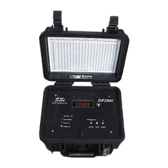
- Page 1 DP2000 Portable Dew Point Analyzer Operations Manual Model DP 2000 Portable Digital Dew Point Analyzer OPERATIONS MANUAL Super Systems Inc. 7205 Edington Drive Cincinnati, OH 45249 513-772-0060 Fax: 513-772-9466 www.supersystems.com Super Systems Inc. Page # 1 of 30...
- Page 2 C.P. 76120 Queretaro, Qro. 200336 Phone: +52 442 210 2459 Phone: +86 21 5206 5701/2 http://www.supersystems.com.mx http://www.supersystems.cn Super Systems India Pvt. Ltd. A-26 Mezzanine Floor, FIEE Complex, Okhla Indl. Area, Phase – 2 New Delhi, India 110 020 Phone: +91 11 41050097 http://www.supersystemsindia.com Super Systems Inc.
-
Page 3: Table Of Contents
ISPLAY READS HIGHER THAN NORMAL AND DOES NOT MATCH OTHER DEW POINT EQUIPMENT RETURNING THE UNIT TO SSI – ......................24 WARRANTY .............................. 26 SPARE PARTS – ............................27 APPENDIX “A” – ............................28 APPENDIX “B” – ............................29 Super Systems Inc. Page # 3 of 30... -
Page 4: Introduction
DP2000 Portable Dew Point Analyzer Operations Manual INTRODUCTION – Thank you for selecting Super Systems Inc. (SSi) and the DP2000 as your source for accurate dew point measurements of: ● Endothermic Atmosphere ● Endothermic Generators ● Nitrogen / Methanol Atmosphere ●... -
Page 5: Warnings
The DP2000 Dew Point Analyzer has been calibrated and fully charged before it was shipped from Super Systems, Inc. You can begin typical operation as soon as the unit has been allowed to stabilize in a temperature similar to the temperature in the heat-treating department. -
Page 6: Operation
Also, make sure that the sample gas is flowing through the filter in the right direction. There is an arrow on the filter to indicate which direction the gas should flow (Figure 4). Figure 3 Figure 4 Super Systems Inc. Page # 6 of 30... - Page 7 Not only will this ensure that the sample reading is not abnormally high (since soot tends to trap moisture), but it will also prevent soot and other contaminants from entering the unit and damaging the sensor. Super Systems Inc. Page # 7 of 30...
-
Page 8: Instrument Damage
When taking a sample from a furnace or a generator, care should be taken to reduce the amount of soot that enters the instrument. The in-line filter will trap these particles, but cleaning the sample line before attaching the DP2000 will Super Systems Inc. Page # 8 of 30... - Page 9 To test if it is operating properly, verify the ambient dew point against a web-based weather station that will report the ambient dew point for your area. If the displayed reading is within Super Systems Inc. Page # 9 of 30...
-
Page 10: What Is Dew Point
Maintaining proper sensor temperature will prevent the premature failure of the sensor. The operating temperature of the sensor should remain below 140 F (60C) at all times. Periodic checks of the sensor temperature will verify that the Super Systems Inc. Page # 10 of 30... -
Page 11: Factory Calibration
It is also possible to calibrate the DP2000 in the field, which will require the optional calibration kit (Part Number 31030). The instructions for a field calibration are shown here, however please feel free to contact Super Systems at if you would like to review the process with us before you begin. - Page 12 Slip the black sensor gland (supplied in the calibration kit) over the sensor probe with the sensor tip protruding from the threaded end of the gland and the sensor wires being flush with the top of the rubber Super Systems Inc. Page # 12 of 30...
- Page 13 Appendix B will show the temperature values in Celsius. Next to the appropriate temperature, note the number in the corresponding column titled “75.3%”. This should match with the dew point that is shown on the display of the DP2000. Super Systems Inc. Page # 13 of 30...
- Page 14 With the power to the unit still turned off, leave the sensor in the calibration salt for a minimum of 24 hours. It is acceptable to leave the sensor in the salt solution for a longer period of time, even a few days, if desired. Super Systems Inc. Page # 14 of 30...
- Page 15 NOTE: Keep in mind that the DP2000 only displays even numbers, and not tenths of a degree. Therefore, a reading of 18°F (-7.8°C) could be as low as 17.50°F (-8.06°C) or as high as 18.49°F (-7.51°C). Super Systems Inc. Page # 15 of 30...
- Page 16 After the unit has passed the leak test, re-fasten the screw into the faceplate and tighten it. 17.0 Make sure that all caps are replaced on the calibration salts, and return the DP2000 to service. Super Systems Inc. Page # 16 of 30...
-
Page 17: Recharging The Model Dp2000
110 VAC outlet. If the unit will power up only when the power cord is plugged in, the battery may be bad. Please contact Super Systems, Inc. at for more information regarding the 513-772-0060 replacement of the battery. -
Page 18: Dew Point Reading Shows +80°F (Or A High Reading) And Never Drops
DP2000 Portable Dew Point Analyzer Operations Manual the unit. Please contact Super Systems, Inc. at for more 513-772-0060 information regarding this issue. Dew point reading shows +80°F (or a high reading) and never drops: The upper range of the sensor is +80°F (27°C). If that value is displayed, it likely indicates the presence of moisture in the sample tubing or on the dew point sensor tip. - Page 19 Dry compressed air is compressed air produced by a facility air compressor that has flowed through a desiccant or refrigerated air dryer with a dew point of 40°F (4°C) or less. Super Systems Inc. Page # 19 of 30...
- Page 20 Sensor Sampling Block. Blow gas through the sampling line for as long as it takes to remove any visible moisture from the line. Reconnect the tubing at both ends. Super Systems Inc. Page # 20 of 30...
- Page 21 Remove the tubing at both ends between the dew point element housing and the inlet of the sample pump (Figure 19). Blow out the tubing to remove the moisture. Reconnect the tubing. Figure 19 Super Systems Inc. Page # 21 of 30...
- Page 22 The wet filter and sample tubing can be re-attached after they have been completely dried out. The filter element will regain all of its original filtering properties after it has dried out. Super Systems Inc. Page # 22 of 30...
-
Page 23: No Visible Flow Is Shown In The Flow Meter
Reconnect the tubing. If this does not help, the seals have probably failed and the pump needs to be replaced. Please contact Super Systems, Inc. at 513-772-0060 more technical support. -
Page 24: Display Appears To Be Locked Up And Never Changes (Not At 80°F)
If soot is allowed to collect on the dew point sensor in the instrument, it could result in higher readings. This soot will also retain moisture than can corrode the sensor over time. Please contact Super Systems, Inc. at 513-772-0060 for more technical support. - Page 25 SSI undamaged. Before shipping the analyzer, please call 513-772-0060 to receive a Return Materials Authorization (RMA) number. The shipping address that should be used for returns is: Super Systems, Inc. ATTN: RMA #XXXX 7245 Edington Drive Cincinnati, OH 45249 Super Systems Inc.
-
Page 26: Warranty
WARRANTY Limited Warranty for Super Systems Products: The Limited Warranty applies to new Super Systems Inc. (SSI) products purchased direct from SSI or from an authorized SSI dealer by the original purchaser for normal use. SSI warrants that a covered product is free from defects in materials and workmanship, with the exceptions stated below. -
Page 27: Spare Parts
33018 Flow meter 36033 Sample Pump 37119 Flexible Sample Tubing Assembly w/Filter A20315 Cell Sampling Block 20192 Sample Tube (wand and valves) 20263 Dew Point Circuit Board 31662 Dew Point Probe 31437 Super Systems Inc. Page # 27 of 30... - Page 28 18.37 67.62 79.70 21.23 71.19 15.58 64.15 18.44 67.72 21.31 71.29 72.40 76.10 79.80 15.65 64.25 18.52 67.82 21.38 71.39 72.50 76.20 79.90 15.73 64.34 18.60 67.91 21.46 71.48 72.60 76.30 80.00 Super Systems Inc. Page # 28 of 30...
- Page 29 -7.57 19.79 26.50 -5.98 21.77 -9.12 17.86 -7.53 19.84 -5.94 21.83 22.44 24.50 26.56 -9.08 17.92 -7.49 19.90 -5.90 21.88 22.50 24.56 26.61 -9.04 17.97 -7.44 19.95 -5.86 21.93 22.56 24.61 26.67 Super Systems Inc. Page # 29 of 30...
- Page 30 Updated manual to current format, added 11-17-2016 2201 warranty text, changed shipping address Updated Spare Parts list (A20315) 07-14-2017 2221 Updated Operation section and Expanded 2/7/2019 2252 Troubleshooting section. Added visuals. Updated Spare Parts list 4/27/2020 2289 Super Systems Inc. Page # 30 of 30...
Need help?
Do you have a question about the DP 2000 and is the answer not in the manual?
Questions and answers