
Related Manuals for MICRO-EPSILON optoNCDT1800


Summary of Contents for MICRO-EPSILON optoNCDT1800
- Page 1 SENSORS & SYSTEMS Authority in Displacement Measurement MICRO-EPSILON Laser Optical Displacement Sensor with high speed CCD-System Instruction Manual optoNCDT1800, 1801...
- Page 2 MICRO-EPSILON MESSTECHNIK GmbH & Co. KG Königbacher Strasse 15 D-94496 Ortenburg Tel. +49/85 42/1 68-0 Fax +49/85 42/1 68-90 e-mail info@micro-epsilon.de www.micro-epsilon.com Certified in compliance with DIN EN ISO 9001: 2000...
-
Page 3: Table Of Contents
Serial Interface (Option) ..........31 RS232 ....................31 RS422/485 .................... 31 Set-up of the Commands ..............32 Available Commands ................33 8.4.1 Information Command ................ 33 8.4.2 Zero Command ................... 34 8.4.3 Average Command 0 ... 3 ..............34 optoNCDT1800, 1801... - Page 4 Optimising the Measuring Accuracy ............ 40 Warranty ............... 41 Decommissioning, Disposal ........41 Appendix ............... 42 12.1 Pin Assignment DSUB Connector ............42 12.2 Protective Housing ................42 12.3 Free Space for Optics ................46 12.4 Service, Repair ..................49 optoNCDT1800, 1801...
-
Page 5: Safety
The housing of the series 1801 controller housing may only be opened by • DANGER! authorised persons. Do not open series 1801 > Danger of injury through mains voltage controller housing! > Damage to or destruction of the controller optoNCDT1800, 1801... -
Page 6: Notes On Ce Identification
336/EEC ‘Electromagnetic Compatibility’ and the European standards (EN) listed therein. The EC declaration of conformity is kept available according to EC regulation, article 10 by the authorities responsible at MICRO-EPSILON MESSTECHNIK GmbH & Co. KG Königbacher Str. 15 94496 Ortenburg... -
Page 7: Laser Class
Although the laser output is low looking directly into the laser beam must be avoided. Due to the visible light beam eye protection is ensured by the natural blink reflex. The housing of the optical sensors optoNCDT1800/1801 may only be opened by the manufacturer. For repair and service purposes the sensors must always be sent to the manufacturer. -
Page 8: Functional Principle, Technical Data
- In range - Mid range - Laser ON/OFF - Power on LEDs on the sensor signal: - Out of Range (upper and lower range values) - Poor Target (unfit or no object) - Mid range - Laser ON/OFF optoNCDT1800, 1801... -
Page 9: Technical Data
The specified data apply for a diffusely reflecting matt white ceramic target. FSO = Full Scale Output SMR = Start of measuring range = Midrange EMR = End of measuring range 1) The data for the sensor are based on DIN EN 60028-2-6 (vibration) and DIN EN 60028-2-29 (shock). optoNCDT1800, 1801... -
Page 10: Block Diagramm
3.3 kOhm Pin 4 Reaction Time for Laser-On: Laser Correct measuring data are ON/OFF I < 10 mA sent by the sensor approximately 11 ms after Pin 17 signal for Laser-On. Controller Fig. 3.2: Electrical wiring for laser on/off optoNCDT1800, 1801... -
Page 11: Delivery
Humidity: 5 - 95 % (no condensation) Installation The optoNCDT1800/1801 is an optical sensor for measurements with micrometer accuracy. Make sure it is handled carefully when installing and operating. MICRO-EPSILON recommends the use of protective housings if the sensor operates in a dirty environment or higher ambient temperature. See also Chap. 11.2. -
Page 12: Mounting Of The Sensor
(.53) 80.0 (3.15) 89.0 (3.50) 97.0 (3.82) Fig. 5.2: Sensor dimensions ILD 1800/1801-2/10/20/50/100/200 (not to scale) The laser beam must be directed perpendicular onto the surface of the target. Misalignment will create measuring errors (indication of bigger distances). optoNCDT1800, 1801... - Page 13 195 (7.68) means of 3 screws type M5. 157.4 (6.20) 122 (4.80) 85 (3.35) 5 (.20) 3 Mounting holes ø6 mm (.24DIA) nach DIN EN 60825-1:2001-11 Laser spot 100 (3.94) Fig. 5.4: Sensor dimensions ILD 1810/1811-50 (not to scale) optoNCDT1800, 1801...
-
Page 14: Mounting Of The Controller
The controller is mounted by means of 4 screws type M4 DIN 84. When mounting the controller keep the LED displays free for watching. Mounting angle 154 (6.06) ø4.5 (.18) 36.5 100 (3.94) (1.44) 173 (6.81) Fig. 5.5: Dimensions of the l l o controller 1800/1801 with mounting angle (not to scale) optoNCDT1800, 1801... -
Page 15: Mains Fuse Controller 1801
• Max. length 10 m (32 ft), the electromagnetic field may cause measurement uncertainty on the signal if you work with cables longer then 10 m (32 ft). MICRO-EPSILON recommends to terminate the end of the cable with 10 nF to avoid noise voltages. -
Page 16: Measuring Setup And Commissioning
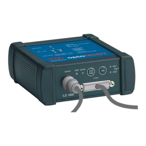
--> Measurement is okay yellow --> Target in mid range --> Target out of range, unfit or no object sensor power state avg 1 zero avg 3 reset avg 2 in/out ILD1800 Fig. 6.1: Front view controller optoNCDT1800, 1801... -
Page 17: Average Setting
- Moving average averaging are saved after switching off. - Recursive average - Median The purpose of averaging is to: - Improve the resolution - Eliminate signal spikes - „Smooth out“ the signal. > optoNCDT1800, 1801... -
Page 18: Averaging Number N
1) When the number of averaging is changed, an error will continue to be sent until the required number of measurement values for the selected averaging count have been reached (logged). For the optoNCDT1800/1801 and a number of averaging of 128, the maximum time required is 26 ms (128 x 0.2 ms = 25.6 ms) -
Page 19: Averaging Type
When the controller is switched on again the next time, the last selected averaging method will be indicated during booting by the momentary illumination of the LEDs “AVG1” and “AVG2”: Tab. 6.3: LEDs display the averaging type during booting optoNCDT1800, 1801... -
Page 20: Moving Average (Default Setting)
However, it requires extremely long transient recovery times for steps in measurement values. The recursive average shows low-pass behaviour. The output frequency stays constant at 5 kHz / 2.5 kHz for the measuring range of 500 mm. Standard values for N: 1, 4, 32, 128 (window width). optoNCDT1800, 1801... -
Page 21: Median
The following diagrams illustrate the impact of the different internal averaging methods: Example 1: Oscillation measurement on a rotating target (unbalaced) with raw surface and scratches Oscillation (avg0) Position value optoNCDT1800, 1801... - Page 22 Individual spikes will be smoothed with greater averaging numbers. Applications: Oscillation measurement, measurements on metal profiles Moving average avg1 (N = 4) Position value Moving average avg2 (N = 32) Position value Moving average avg3 (N = 128) Position value optoNCDT1800, 1801...
- Page 23 Impact: Removes individual spikes (e.g. scratches on the surface) without any reduction in the vibration amplitude, thereby low noise suppression. Applications: Fast measurements on metal profiles. Median avg0 (about 3) Position value Median avg3 (about 9) Position value optoNCDT1800, 1801...
- Page 24 Applications: Measurements on metal surfaces, vibration and unbalance measurements Moving average avg1 (N = 4) Position value Moving average avg2 (N = 32) Position value Moving average avg3 (N = 128) Position value optoNCDT1800, 1801...
- Page 25 Position value Median (N = 9) Position value Recursive averaging Impact: Reduces the surface noise and the vibration amplitude, strong smoothing of the wave form. Applications: Measurements on non-profiled belt-type materials Recursive average (N = 256) Position value optoNCDT1800, 1801...
-
Page 26: Adjustment Of Zero-Point
Pin Assignment DSUB Connector of the sensor. a t l > ≤ l o i ) - ( < ) - ( > e t i ) - ( ) - ( optoNCDT1800, 1801... -
Page 27: Responses Of The Analog Output To Errors
(see Chapter 6.3. Zero-Point) • Pressing and holding the Zero/Reset key for longer (> 5 secs) will cancel the zero shift (offset) and set the number of averaging to N = 1 (for the median N = 3). optoNCDT1800, 1801... -
Page 28: Error Output Circuit
22 (+) OUT OF RANGE (upper and lower range values) 9 (-) Synchronization If two or more optoNCDT1800/1801 measure against the same target, the controller can be synchronized. Connect the output Sync out of controller 1 with the input Sync in of controller 2. -
Page 29: Timing
600 μs. The processing of the cycles occurs sequentially in time and parallel in space (see Tab. 6.5, pipelining). This guarantees a true constant real time data stream. μ μ μ μ Tab. 6.5: Controller Timing optoNCDT1800, 1801... -
Page 30: Measurement Value Output
* 6.23167e-5 - 0.51) * 10 mm = -4.99967 mm (SMR) Digital Error Codes Value range 16368 ... 16383 (digital F1 bad objekt 16370 F2 out of range + 16372 F3 out of range - 16374 F4 poor target 16376 F5 Laser off 16378 optoNCDT1800, 1801... -
Page 31: Serial Interface (Option)
Serial Interface (Option) MICRO-EPSILON Serial Interface (Option) The optoNCDT1800/1801 controller can be operated with a PC if the ssystem has a digital interface (RS232 or RS485). This manual describes the communication protocol between a PC and the sensor optoNCDT1800/1801. RS232 IMPORTANT! The RS232 module uses the RS232 standard (EIA/TIA-232-E resp. -
Page 32: Set-Up Of The Commands
MICRO-EPSILON The data word consists of two consecutive bytes which are transmitted in series without a identity bit. Use the IF2004 interface card (available from MICRO-EPSILON) for communication with a PC. Interface card and controller are connected with the PC1800-3/10/RS485 interface cable (available from MICRO-EPSILON). The interface card combines the both bytes from the data word and storages it as a 16 bit value in the FIFO. -
Page 33: Available Commands
Information Command Name: INFO Description: Sensor data are sent in ASCII format when the command is returned. 7.4 Zero Command Format: " " " " " " " l " " " L " " D " " 1 optoNCDT1800, 1801... -
Page 34: Zero Command
" " l " " " L " " D " " 1 0x70 AVG0 0x71 AVG1 0x72 AVG2 Response: 0x73 AVG3 " l " " " L " " D " " 1 AVG0 AVG1 AVG2 AVG3 optoNCDT1800, 1801... -
Page 35: Average Command N
Parameter X: 0 = Recursive Average " " " " " " 1 = Moving Average " l " " " L " " D " " 1 (Standard) 2 = Median Value for X (0, 1, 2) optoNCDT1800, 1801... -
Page 36: Reset Command
" L " " D " " 1 Note: When switching the sensor on data output is on. The "stop" command is transient and will be lost when switching off the power supply or when sending the reset command. optoNCDT1800, 1801... -
Page 37: Stop Command
Name DISPLACEMENT Description Changes to displacement measurement. Format: " " " " " " " l " " " L " " D " " 1 Response: " l " " " L " " " " 1 optoNCDT1800, 1801... -
Page 38: Thickness Command
Up to three layers can be measured. " " " " " " " l " " " L " " D " " 1 Response: " l " " " L " " D " " 1 optoNCDT1800, 1801... -
Page 39: Instructions For Operating
Due to the damping effect of the heat capacity of the sensor sudden temperature changes are only measured with delay. Laser beam Laser beam Laser beam Ideal diffuse reflection Direct mirror Real reflection, usually mixed reflection Fig. 9.1: Reflection factor of the target surface optoNCDT1800, 1801... -
Page 40: Mechanical Vibration
The same arrangement must be used for colour strips (fig. 9.3). Colour strips Direction of movement ILD 180x Grinding or rolling marks Fig. 9.3: Sensor arrangement in case of ground or striped surfaces optoNCDT1800, 1801... -
Page 41: Warranty
MICRO-EPSILON will specifically not be responsible for eventual consequential damages. MICRO-EPSILON always strives to supply the customers with the finest and most advanced equipment. Development and refinement is therefore performed continuously and the right to design changes without prior notice is accordingly reserved. -
Page 42: Appendix
Installation of the sensors in the protective housings should be performed by the manufacturer, because especially in case of short reference distances the protective window must be included in the calibration. optoNCDT1800, 1801... - Page 43 SGH1800/1801 (Not to scale) 4 Mounting holes ø4.5 (.18DIA.) Fig. 12.1: Protective housing for Sensor cable with Air inlet measuring ranges 2/10/20/50/ connector (Air supply can be pivoted, for flexible 100/200 mm tube with 6 mm inner diameter) optoNCDT1800, 1801...
- Page 44 (.18DIA) blind plug For SGH2200: (without air Legend: purging) Laser Exhaust air spot (inches) 25.5 (1.00) connector Sensor cable with connector 6.5 (.26) 103 (4.06) 140 (5.51) 168 (6.61) Fig. 12.2: Protective housing for measuring range 500/750 mm optoNCDT1800, 1801...
- Page 45 MICRO-EPSILON SGHF1810-50 Laser spot (Not to scale) Laser spot Sensor cable with connector Legend: (inches) 4 Mounting holes ø4.5 (.18DIA.) 18.5 4 (.16) (.73) 141.5 (5.57) 160 (6.30) 188 (7.40) Fig. 12.3: Protective housing for the sensor optoNCDT1810-50 optoNCDT1800, 1801...
-
Page 46: Free Space For Optics
(inches) (.53) (.59) Start of measuring range End of measuring range Fig. 11.4: Free space for measuring ranges 2/10/20/50/100/200 mm ° ° ° ° ° ° ° ° ° ° ° ° ° ° ° ° ° ° optoNCDT1800, 1801... - Page 47 130 (5.12) 101 (3.98) 85 (3.35) 12 (.47) dia. 5 (.20) 17.5 (.59) (.69) 35 (1.38) Start of measuring range End of measuring range Fig. 12.5: Free space for measuring ranges 500/750 mm ° ° ° ° ° ° optoNCDT1800, 1801...
- Page 48 Appendix MICRO-EPSILON 200 (7.87) 48 (1.89) 161 (6.34) 14 (.55) (.94) ø30 ø5 (.20) ø 30 (1.18) (1.18) Start of measuring range End of measuring range Fig. 12.6: Free space for the sensor optoNCDT1810-50 optoNCDT1800, 1801...
-
Page 49: Service, Repair
In the event of a defect in the sensor, sensor cable or controller the whole measuring system must be sent back for repair or replacement. In the case of faults the cause of which is not clearly identifiable, the whole measuring system must be sent back to MICRO-EPSILON Optronic GmbH Lessingstraße 14 D-01465 Langebrück... - Page 50 MICRO-EPSILON optoNCDT1800, 1801...
- Page 51 MICRO-EPSILON optoNCDT1800, 1801...
- Page 52 MICRO -EPSIL -EPSILON worldwide -EPSIL ON worldwide ON worldwide ON worldwide MICRO MICRO -EPSIL ON worldwide .micro-epsilon.com .micro-epsilon.com www.micro-epsilon.com .micro-epsilon.com .micro-epsilon.com Headquarter MICRO-EPSILON MESSTECHNIK Königbacher Strasse 15 D-94496 Ortenburg Tel: +49/8542/1 68-0 Fax: +49/85 42/1 68-90 e-mail: info@micro-epsilon.de X9751053-C081080RLA *X9751053-C08*...
Need help?
Do you have a question about the optoNCDT1800 and is the answer not in the manual?
Questions and answers