
Related Manuals for Eagle 2000F Series


Summary of Contents for Eagle 2000F Series
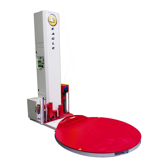
- Page 1 Operations Manual Eagle 2000F Series Stretch Wrapper READ ALL INSTRUCTIONS CONTAINED IN THIS MANUAL PRIOR TO MACHINE INSTALLATION! - 1 -...
-
Page 2: Table Of Contents
Contents page Machine Safety Information Safety & Warnings Specifications Outline & Applications Position of Operation Safety Precautions Prior to Operation Machine Installation Machine Structure & Main Components Transportation Installation Operational Environment Operation Operational Steps & Film Loading Basic Machine Operation LCD Screen Operation LCD Screen Navigation &... -
Page 3: Safety & Warnings
1.1 Safety & Warnings Before servicing, always power down and unplug the machine from the power source. Ensure that the correct voltage is being supplied from the power source. Do not touch the turn table while machine is in operation. ... - Page 4 1.1 Safety & Warnings DO NOT MODIFY OR REMOVE WARNING LABELS Film Carriage Do Not Open While Running Control Panel (Bottom) Electrical Hazard Do not service machine while powered up and connected to power source! - 4 -...
-
Page 5: Specifications
1.2 Specifications - Eagle 2000F Power Supply 110VAC, 60Hz Air Supply 80 PSI Turntable Speed (Standard 0-12 rpm) (Optional 0-20rpm) Turntable Motor 1 HP 750W 1420 RPM 220V 1:30 Gearbox Turntable Diameter 64.9” Turntable Diagonal 58” Turntable Height 3.4” Turntable Gear... -
Page 6: Position Of Operation
1.3 Outline and Application Field This machine features a PLC controller. The electric subassembly uses world famous products such as OMRON, LG and TE components. This provides a reasonable, high reliability and convenient use for the machine. It can advance production efficiency and prevent goods from being damaged during transportation. - Page 7 2.1 Machine Structure & Components Illustration Mast Control Panel Film Carriage Turntable Fig. 2-1 - 7 -...
-
Page 8: Transportation
2.2 Transportation You must have at least 4ft fork tubes or tube extensions fully inserted into the machine and a forklift rated for 3,000lbs to transport the machine safely. Do not raise the load more than 6” off of the ground. -
Page 9: Installation
2.3 Installation Step 1 - Place the machine in the desired location using a tow motor or crane capable of handling a load of 3,000lbs. (See Fig. 2-3) Fig. 2-3 Step 2 - Remove the lower rear inspection panel on the mast prior to raising the mast. The panel is located on the end of the machine next to the turntable motor The panel has a warning label affixed to it. - Page 10 2.3 Installation Step 4 - If installing a ramp, place the ramp by locating the ramp shoulder bolt and placing it into the slot in the ramp. It is highly recommended to anchor the ramp to the floor. (See Fig. 2-6) Fig.
- Page 11 2.3 Installation Step 6 - Insert the connector plug inside the bottom of the mast into the corresponding receptacles. (See Fig 2-9a, 2-9b, 2-9c) Fig. 2-9a Fig. 2-9b Fig. 2-9c Note: These connectors are for carriage motor power (pre-stretch), photo-electric eye, home limit switch, and E-Stop switch located on the bottom of the carriage.
-
Page 12: Operational Environment
2.4 Operational Environment • Machine should be far from smoke, preferably in a dry, well-ventilated area. • Normal environment temperature should be within 32ºF and 104ºF. • No special requirements for electromagnetic radiation. • Machine should not be placed under direct lighting as it may cause photoelectric eye to malfunction. -
Page 13: Operational Steps & Film Loading
3.1 Operational Steps & Film Loading BEFORE LOADING FILM, PRESS THE EMERGENCY STOP BUTTON AND TURN THE POWER SWITCH TO THE OFF POSITION Loading stretch film into carriage Step 1 - Loosen fastening screw "A" and take off roll holder "B". (See Fig. -
Page 14: Basic Machine Operation
If the table speed is decreased, the load force will need to be increased to maintain the same film tension. The Eagle 2000F can be operated remotely by use of a hand-held controller. This allows the machine operator to run and stop the stretch wrapper wirelessly. -
Page 15: Lcd Screen Operation
3.3 LCD Screen Operation The LCD screen displays information used to control the machine and to make changes to operational parameters. Active keys are shown with a circle or square around them. Pressing the corresponding key will execute the function. To change a setting, press the SET button. - Page 16 3.4 Navigating LCD Screens Menu From this screen, you can navigate to; ① Mode, ② Job Count, ③ View Parameters, ④ Settings Parameter Settings / page 1 From this screen, you can set; Top Wraps, Bottom Wraps, and number of Up & Down cycles Parameter Settings / page 2 From this screen, you can set;...
- Page 17 3.4 Navigating LCD Screens Job Mode From this screen, you can select the different types of modes the machine has. Job Mode / Auto This mode is used to automatically wrap packages. To begin, press Start button Note: The film clamp must be closed to start a job. To manually close the film clamp, press either the film clamp button to the front of the ⓪...
- Page 18 3.4 Navigating LCD Screens Job Count This screen displays the current number of cycles and the total number of cycles of the machine. To reset the current yield, press the ALM button - 18 -...
- Page 19 4.1 Weight Scale - Introduction & System Overview Operation / Function ON / OFF Turns Scale On / Off Press and hold for 2+ seconds to operate Hold Hold Weight on Scale (Manual Hold) Press 'Hold' with scale loaded. ...
- Page 20 4.1 Weight Scale - Introduction & System Overview Total Add Weights With package on the scale, press the 'Total' key to enter weight and retain in memory. Press 'Total' after weighing each package to add weight to cumulative total. ...
-
Page 21: Error Codes
4.2 Weight Scale - Error Codes Error Code Possible Cause Solution uuuuuu Overloaded condition. Reduce the weight. Wrong connection at load cell. Check load cell connection Load cell has quality problem. Inspect load cell for damage. ... -
Page 22: Troubleshooting Guide
5.1 Troubleshooting Guide Error Code Possible Cause Solution Machine will not function Machine not plugged in. Plug machine into 110VAC Outlet where Machine is plugged outlet. into has no power or bad outlet. Check to see if outlet has power. ... - Page 23 5.1 Troubleshooting Guide Problem Possible Causes Solution Carriage Check to see if the machine is plugged in. Plug machine into adequate Check carriage speed knob is at minimum power 110 Volt outlet. does not run. position – if so turn carriage speed knob to a Replace chain or reinstall chain / ...
-
Page 24: Carriage Load Safety Switch
5.2 Carriage Load Safety Switch USE EXTREME CAUTION WHEN ADJUSTING CARRIAGE SWITCH AS IT CAN BE DAMAGED BY OVER ADJUSTMENT Step 1 - Open Carriage Door Step 2 - Unload any and all stretch film from machine Step 3 - Loosen jam nut Step 4 - Loosen bolt in small increments to avoid damage to switch Step 5 - Close carriage door gently (Do not install stretch film) Step 6 - If the machine is able to reset, then the carriage door switch... -
Page 25: Turntable Home Switch
5.3 Turntable Home Switch BE SURE TO DISCONNECT POWER AND AIR SUPPLY TO THE MACHINE PRIOR TO ANY MAINTENANCE WORK Fig. 4-1 Fig. 4-2 Turntable Remove the six M10 flat head cap screws in the turn table. Screw in one M10 eyebolt rated for lifting into the tapped hole in the turn plate. Lift the turn table using a hoist and chain rated for a 500lb load. - Page 26 5.3 Turntable Home Switch Fig. 4-4 Remove all 24 idler wheels supporting the turntable rotation if there is excessive bearing play. If the diameter is less than 53mm or there is abnormal noise during operation, replace the bad contact rollers. (See Fig.
-
Page 27: Turntable & Carriage Adjustment
5.4 Turntable & Carriage Adjustment Test Operation Turntable Turn on the power From the Main Menu, press; o ② Job Mode o ② Manual Mode o ⑤ Turntable (starts turntable rotation) o ⑤ Turntable (stops turntable rotation) Verify there is no play in the turntable and that the fasteners are tight. ... -
Page 28: Base (Turntable)
6.1 Illustration Base - 28 -... - Page 29 - 29 -...
- Page 30 6.1 Illustration Base (continued) Name Part Number Turntable FG-023F Base FG-7000 Roller Assembly FG-013A Large Sprocket FG-008 Travel Switch Touch Block FG-009 Chain Tensioner FG-012 Tensioner Sprocket FG-021 Travel Switch (turn counter) TZ-918 Chain Adjustment Screw (main motor) M10x50 Cover Plate 1 FG-7002 Cover Plate 2 FG-7003...
- Page 31 6.2 Illustration Idler Wheel Name Part Number Idler Wheel Bracket Idler Wheel Axle FG-01A-24 Idler Outer Bushing FG-01A-23 Idler Bearing 60202 Idler Wheel FG-01A-21 Idler Wheel Snap Ring 98455A137 Washer 98454A136 - 31 -...
-
Page 32: Mast
6.3 Illustration Mast - 32 -... - Page 33 6.3 Illustration Mast (continued) Name Part Number Mast Cover FG-001-21 Mast FG-002A Motor MVRV040/60- YS6334/B14 Motor Shaft FG-058 Bracket FG-063 Travel Switch XCKP2145 Travel Switch Block FG-08-21 Chain Adjustment Screw FG-065 Slip Block FG-069 Slip Track FG-057 Chain Motorized Sprocket FG-061 Shaft FG-059...
-
Page 34: Carriage
6.4 Illustration Carriage - 34 -... - Page 35 6.4 Illustration Carriage – Continued from previous page. Name Part Number Motor Cover FG-123 Pre-Stretch Motor NMRV040/20- YS6334-B14 Upper Cover FG-111C Bearing Base FG-132 Pre-Stretch Roller FG-114 Tightening Ring FG-038A Tightening Screw Film-Positioning Plate FG-135A Film Shaft FG-134 Micro Switch Frame 1060.180.1.PL Positioning Ring FG-2526...
- Page 36 Swing Shaft (short) FG-142 Micro Switch MQS-216 - 36 -...
-
Page 37: Film Roller
6.5 Illustration Film Roller Name Part Number E-Clip 4-MM-EC-2 Outer Tube Roll Roller Bearing FG-BR-02 Inner Shaft Roller Assembly FG-08-07 - 37 -... -
Page 38: Extended Rollers
6.6 Illustration Extended Roller Name Part Number E-Clip 4-MM-EC-2 Outer Tube Roll Roller Bearing FG-BR-02 Inner Shaft Roller Assembly FG-08-07 - 38 -... - Page 39 6.7 Illustration Film Lift & Cutting Assembly - 39 -...
- Page 40 6.7 Illustration Film Lift & Cutting Assembly – Continued from previous page. Name Part Number Swing Pole FG-726F Swing Pole Fixed Block FG-725D Swing Axis FG-722F Swing Pole Frame FG-2923B Film Picking Cylinder DGP-18-200-PPV-A-B Swing Pole Bracket FG-620F Film Picking Pole FG-8280 Film Brush Frame FG-727F...
- Page 41 6.7 Illustration Film Nipping Device Assembly - 41 -...
- Page 42 6.7 Illustration Film Nipping Device Assembly – Continued from previous page. Name Part Number Film Nip Bracket FG-3211 Transition Frame FG-3255 Bearing Seat FG-3253 Bearing 6094 Gear FG-3251 Driven Chain Wheel FG-3258 Film Nip Bearing Fixed Seat FG-132 Transition Axis 2 FG-3257 Transition Axis 1 FG-3256...
-
Page 43: Electrical Schematics
7. Electrical Schematics - 43 -... - Page 44 7. Electrical Schematics - 44 -...
- Page 45 7. Electrical Schematics - 45 -...
- Page 46 7. Electrical Schematics - 46 -...
- Page 47 7. Electrical Schematics - 47 -...
- Page 48 7. Electrical Schematics - 48 -...
- Page 49 7. Electrical Schematics - 49 -...
Need help?
Do you have a question about the 2000F Series and is the answer not in the manual?
Questions and answers