
Related Manuals for Eagle 100


Summary of Contents for Eagle 100
- Page 1 Operations Manual Eagle 100 Strapping Machine READ ALL INSTRUCTIONS CONTAINED IN THIS MANUAL PRIOR TO MACHINE INSTALLATION! - 1 -...
- Page 2 Contents page Machine Specifications Machine Safety Information Operational Safety Environmental Considerations Machine Transportation Operator Position Machine Operation Control Panel Functions Feeding Strap Machine Operation Maintenance & Troubleshooting Routine Maintenance Lubrication Decelerator Proximity Switch Strap Feed Position Adjustments Troubleshooting Main Parts, Illustrations & Parts List Commonly Replaced Parts Main Parts, Parts Illustrations &...
-
Page 3: Specifications
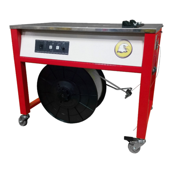
1. Introduction & Specifications Introduction This manual contains safety, operating, and maintenance instructions for the Eagle 100 semi- automatic power strapping machine. This model is designed to strap packages with plastic strap 1/4- 5/8in (6-15mm) wide. The strap ends are joined by means of a hot knife welding process. -
Page 4: Electrical System
Electrical System An all new electrical system using solid state technology supplies continual power to the components within the machine. Using simple to insert circuit boards, the Eagle 100 provides for safe and relatively maintenance-free operation. Operator Controls The electrical control panel consists of the following control switches/buttons;... - Page 5 2. Components - 5 -...
- Page 6 2. Components - 6 -...
-
Page 7: Installation
7. 2.5mm allen wrench Installation Installation of the Eagle 100 requires placing the tension spring (part number 2201210020) into the machine and securing it in place using the included caster, spring retainer, and top cover locks. The screw on the top cap of the speed reducer can be removed for ventilation. -
Page 8: Operation
4. Operation 4.1 Operator Controls The control panel is located on the left-hand side of the front panel of the machine. Power Switch a. Press the power switch to turn on power to the electrical circuits and the electric motor. The button will illuminate to show that power has been turned on. -
Page 9: Loading Strap
4. Operation 4.4 Loading Strap 1. Pull strap out from the strap reel and check whether the strap head is down. If not, then the strap reel needs to be turned such that the strap feeds out from the bottom of pulley “A” and from the top of pulley “B”. -
Page 10: Temperature Adjustment
4. Operation 4.5 Lubrication 1. Lubricate the left knife, middle knife, and right knife of the slide plate once per month 2. The area where the shaft, core, and bearing should be lubricated once every three months. 3. Engine oil should be applied to the gearbox of the decelerator once every two years. 4. - Page 11 4.8 Strap Width Adjustment The Eagle 100 accepts strapping material with a width between 6mm and 15mm. To adjust for a given strap width, adjust the strap insertion hole, the spacing block of the strap output, and the spacing block width.
- Page 12 - 12 -...
- Page 13 4. Operation 4.9 Strap Output Adjustment In the control cabinet, above the circuit board, open the cover plate of the control panel to access the strap output control. By turning the potentiometer in a clockwise direction, strap output can be increased.
-
Page 14: Maintenance And Troubleshooting
5. Maintenance & Troubleshooting 5.1 Regular Maintenance 1. The sliding plate, left guide rail and right guide rail, should all fit exactly and the forward movement of the sliding plate must be smooth. a. Remove the tension spring below the sliding plate. b. - Page 15 6. Illustrations & Parts List 6.1 Main Parts & Components - 15 -...
- Page 16 6. Illustrations & Parts List Main Parts & Components (Continued) Description Part Number Gear Shaft Main Motor Combination Left Guide Rail Sliding Plate Extension Spring (x2) Left Knife Oblique Gear Shaft Right Guide Rail Middle Knife 10 Bearing 16002 11 Right Knife 12 Spacing Sleeve 13 Right Wallboard 14 Roller Wallboard...
- Page 17 6. Illustrations & Parts List 6.1 Main Parts & Components (Continued) 33 Bullet Head 34 Extension spring (x3) 35 Driven Roller 36 Driving Roller 37 Seat Pad 38 Cavity Base 39 Pendulum Bar Tongue 40 Extension spring (x1) 41 Bearing 42 Feeding and Returning Motor Combination 43 Cushion Ring 44 Induction Disk...
- Page 18 6. Illustrations & Parts List 6.1 Main Parts & Components (Continued) 61 Cam (2) 62 Cam (1) 63 Left Wallboard 64 Big Gear Wheel 65 Electric Magnet 66 Spacing Plate of Strap Inserting Path 67 Strap Feeding Bottom Plate 68 Spacing Plate 69 Strap Feeding Pressure Plate 70 Strap Inserting Path Bottom Plate - 18 -...
Need help?
Do you have a question about the 100 and is the answer not in the manual?
Questions and answers