
Related Manuals for Kelly KLS6040S


Summary of Contents for Kelly KLS6040S
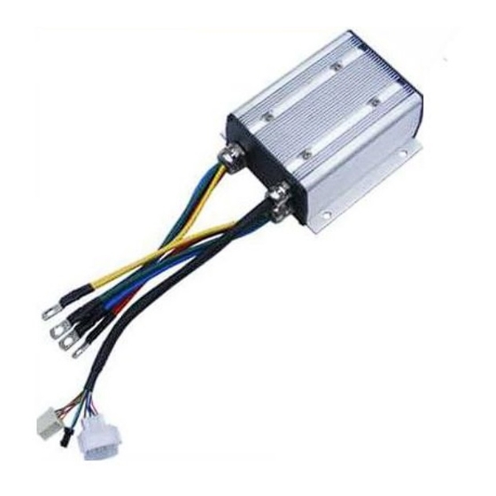
- Page 1 Kelly KLS-S Brushless Motor Controller User’s Manual V1.5.02 Kelly KLS-S Brushless Motor Controller User’s Manual Devices Supported: KLS4812S KLS7212S KLS6018S KLS7230S KLS6025S KLS6040S KLS6030S KLS7240S Rev1.5.02 Sep.2015...
-
Page 2: Table Of Contents
Kelly KLS-S Brushless Motor Controller User’s Manual V1.5.02 Contents Chapter 1 Introduction ....................1.1 Overview..........................2 Chapter 2 Features and Specifications ..............2.1 General functions....................... 3 2.2 Features..........................4 2.3 Specifications........................5 2.4 Name Regulation........................5 Chapter 3 Wiring and Installation ................ -
Page 3: Chapter 1 Introduction
This manual introduces the Kelly Small sinusoidal wave brushless BLDC motor controllers’ features, their installation and their maintenance. Read the manual carefully and thoroughly before using the controller. If you have any questions, please contact the support center of Kelly Controls, LLC. -
Page 4: Chapter 2 Features And Specifications
Kelly KLS-S Brushless Motor Controller User’s Manual V1.5.02 Chapter 2 Features and Specifications 2.1 General functions (1) Extended fault detection and protection. The LED flashing pattern indicates the fault sources.Customers can read the error code in PC software or Android Tablet also. -
Page 5: Features
Kelly KLS-S Brushless Motor Controller User’s Manual V1.5.02 2.2 Features 1) Intelligence with powerful microprocessor. 2) Synchronous rectification, ultra low drop, fast SVPWM and FOC to achieve very high efficiency. 3) Electronic reversing. 4) Voltage monitoring on 3 motor phases, bus, and power supply. -
Page 6: Specifications
2.4 Name Regulation The name regulation of Kelly BLDC motor controllers KLS 72 30S KLS:Kelly BLDC motor controller based on sinusoidal waveform which is supposed to work with BLDC motor with three hall sensors. 72:72V batteries 30:The matched motor is 72V 3KW BLDC motor with hall sensors. -
Page 7: Chapter 3 Wiring And Installation
Kelly KLS-S Brushless Motor Controller User’s Manual V1.5.02 Chapter 3 Wiring and Installation 3.1 Mounting the Controller The controller can be oriented in any position which should be as clean and dry as possible, and if necessary, shielded with a cover to protect it from water and contaminants. - Page 8 Kelly KLS-S Brushless Motor Controller User’s Manual V1.5.02 mounting holes’ dimensions (dimensions in millimeters) Figure 2:KLS6018S...
- Page 9 Kelly KLS-S Brushless Motor Controller User’s Manual V1.5.02 mounting holes’ dimensions (dimensions in millimeters) Figure 3:KLS6025S...
- Page 10 Kelly KLS-S Brushless Motor Controller User’s Manual V1.5.02 mounting holes’ dimensions (dimensions in millimeters) Figure 4:KLS6030S KLS7230S...
- Page 11 Kelly KLS-S Brushless Motor Controller User’s Manual V1.5.02 mounting holes’ dimensions (dimensions in millimeters) Figure 5:KLS6040S KLS7240S...
-
Page 12: Connections
Kelly KLS-S Brushless Motor Controller User’s Manual V1.5.02 3.2 Connections 3.2.1 Pin definition of KLS-S Controller waterproof connector Figure 6: DJ7091Y-2.3-11 Pin Definition (14) REV_SW: Reverse switch input. Orange (6) RTN: Signal return or power supply return. Black (12) FWD: Forward switch White (11) 12V:12V Source Red (9) Relay: Main contactor driver. - Page 13 Kelly KLS-S Brushless Motor Controller User’s Manual V1.5.02 DJ7091Y-2.3-21 Pin Definition (15) Micro_SW: Throttle switch input. Gray (3) Throttle: Throttle analog input, 0-5V. Dark Green (1) Temp: Motor temperature sensor input. Raddle. (20) RTN: Signal return. Black (8) Meter: Copy signal of hall sensors. Dark Blue (4) 5V: 5V supply output, <40mA.
- Page 14 Kelly KLS-S Brushless Motor Controller User’s Manual V1.5.02 3.2.2 Wiring of KLS-S Controller 3.2.2.1 Standard wiring of KLS-S controller Figure 7: KLS-S controller standard wiring (Battery voltage can be used for controller supply)
- Page 15 Kelly KLS-S Brushless Motor Controller User’s Manual V1.5.02 3.2.2.2 Optional wiring of KLS-S controller The 12V input signal of the pin supplies the second braking function of the controller. Figure 8: Wiring of brake switch(12V): 12V is provided by external source.
-
Page 16: Installation Check List
Kelly KLS-S Brushless Motor Controller User’s Manual V1.5.02 3.2.3 Communication Port A 4pin connector to RS232 port is provided to communicate with host computer for calibration and configuration. Figure 8: RS232 Interface on 4pin connector to RS232 converter Figure 9:SM-4P connector for communication interface on KLS-S controller 3.3 Installation Check List... -
Page 17: Chapter 4 Programmable Parameters
Kelly KLS-S Brushless Motor Controller User’s Manual V1.5.02 • The fault code will be detected automatically at restart. • With the brake switch open, select a direction and operate the throttle. The motor should spin in the selected direction. Verify wiring or voltage and the fuse if it does not. The motor should run faster with increasing throttle. - Page 18 (7)TPS High Err: Hall active pedal, if higher than the value, report the fault of TPS Type. Range: 80~100 As you may know,the output of hall throttle from Kelly is about from 0.86V to 4.2V. Our controller will report 3.3 error code if the output of hall throttle is below 0.5V or above 4.5V by default.
- Page 19 Kelly KLS-S Brushless Motor Controller User’s Manual V1.5.02 (8)TPS Type: TPS Type, 1:0-5V 3-wire 0-5K pot,5K is normal,2K-20K can be used;2:Hall active throttle or pedal. Range: 1~2 (9)TPS Dead Low: TPS Dead Zone Low. Range: 5~40 Functional description: Set throttle effective starting point Suggestion: Set according to the practical situation, factory default is 20%*5V=1.0V.
- Page 20 Kelly KLS-S Brushless Motor Controller User’s Manual V1.5.02 function is enabled. If enable,the controller will detect the current pedal position or signal When the switch is in neutral poistion. If the throttle got effective output signal,the controller will not operate and report fault code.
-
Page 21: Step 2
Kelly KLS-S Brushless Motor Controller User’s Manual V1.5.02 Reverse Forward Forward Disable Disable Reverse Note: X means can be on or off Figure 4.2 (21)Boost:If enabled,the controller will output max power for a while. Boost function is just full throttle position when you turn on boost switch even if the throttle is not operated at all. -
Page 22: Step 3
Kelly KLS-S Brushless Motor Controller User’s Manual V1.5.02 If you have a motor with 5V,Sin/Cosin,GND speed sensors,please choose it at 4.And please inquire the KLS-8080IPS model before ordering. (3)Resolver Poles: Resolver Poles, The pair pole number*2. Range: 2~32 It is only used for the Resolver sensor type. - Page 23 Kelly KLS-S Brushless Motor Controller User’s Manual V1.5.02 Factory set is 0 (2)NTL Brk %: NTL Braking Percent, the percent of Neutral Braking in max braking. Range: 0~50 Only useful when you enable Three gears switch in user program. The regen will happen when you turn F-N-R switch from Forward or backward to Neutral position.
-
Page 24: Chapter 5 Maintenance
Identification angle operation. • Use a straight through RS232 cable or USB converter provided by Kelly to connect to a host computer. Provide >+18V to PWR(for a 24V controller, provide >+8V). Wire power supply return(supply negative) to any RTN pin. - Page 25 V1.5.02 • KLS controller requires a 4pin connector to Kelly RS232 Converter to support the communication.And customers may need a Z-TEK USB cable for Tablet with Android OS. Customers may download PC software or Android APP to program the controller before running the motor.You may do Identification angle operation for brushless...
- Page 26 B- or RTN. 2. There may be excessive load on the +5V supply caused by too low a value of Regen or throttle potentiometers or incorrect wiring. 3. Controller is damaged. Contact Kelly about a warranty repair. Over temperature ¤¤...
-
Page 27: Contact Us
Kelly KLS-S Brushless Motor Controller User’s Manual V1.5.02 motor temperature cools down. The Red LED flashes once at power on as a confidence check and then normally stays Off. “1, 2” means the Red flashes once and after a second pause, flashes twice. The pause time between multiple flash code groups is two seconds.
Need help?
Do you have a question about the KLS6040S and is the answer not in the manual?
Questions and answers