Kelly KLS7212N User Manual
Brushless motor controller
Hide thumbs
Also See for KLS7212N:
- User manual (40 pages) ,
- User manual (37 pages) ,
- User manual (37 pages)

Related Manuals for Kelly KLS7212N


Summary of Contents for Kelly KLS7212N
- Page 1 Kelly KLS-N Brushless Motor Controller User’s Manual V2.6 Kelly KLS-N Brushless Motor Controller User’s Manual Devices Supported: KLS7212N KLS7215N KLS7218N KLS7222N KLS6018N KLS6030N KLS7230N KLS7245N KLS7250N...
- Page 2 Kelly KLS-N Brushless Motor Controller User’s Manual V 2.6 Rev.2.6 DEC.2019...
-
Page 4: Table Of Contents
Kelly KLS-N Brushless Motor Controller User’s Manual V2.6 Contents Chapter 1 Introduction ................. 2 1.1 Overview ................... 2 Chapter 2 Features and Specifications ............3 2.1 General functions ................3 2.2 Features .................... 4 2.3 Specifications ..................5 2.4 Name Regulation ................5 Chapter 3 Wiring and Installation .............. -
Page 5: Chapter 1 Introduction
This manual introduces the Kelly sinusoidal wave brushless BLDC motor controllers’ features, their installation and their maintenance. Read the manual carefully and thoroughly before using the controller. If you have any questions, please contact the support center of Kelly Controls. -
Page 6: Chapter 2 Features And Specifications
Kelly KLS-N Brushless Motor Controller User’s Manual V 2.6 Chapter 2 Features and Specifications 2.1 General functions (1) Extended fault detection and protection. Customers can read the error message in PC software or Android APP also. (2) Monitoring battery voltage. It will stop driving if the battery voltage is too high and it will progressively cut back motor drive power as battery voltage drops until it cuts out altogether at the preset “Low Battery Voltage”... -
Page 7: Features
Kelly KLS-N Brushless Motor Controller User’s Manual V 2.5 (23)Bluetooth function.Required a small Bluetooth converter which needs to be purchased in addition from our website.This small converter is only useful for KLS controller. Caution! The regen is not a safe function.Usually you may use the mechanical brake. -
Page 8: Specifications
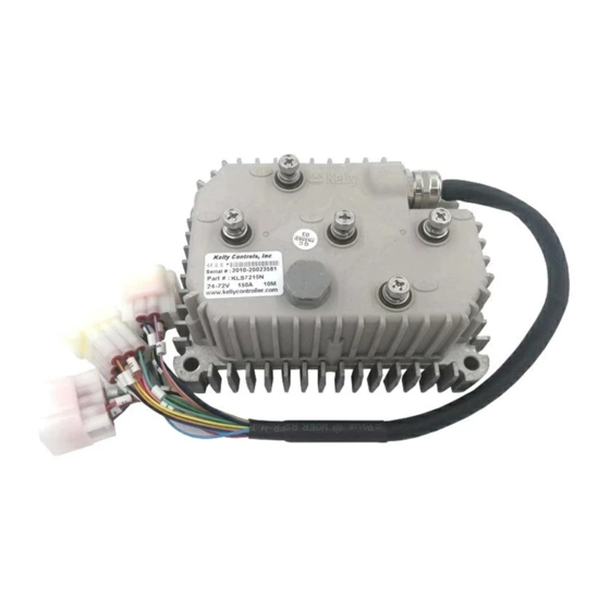
N: The motor controller included a plastic cover. And KLS-N is IP66 rating without filling the silica gel by default. KLS-N used cast aluminum box as body protection. KLS7212N: The only KLS controller used the solid flat aluminum plate as bottom of controller. The thickness of plate is 8mm. -
Page 9: Chapter 3 Wiring And Installation
Kelly KLS-N Brushless Motor Controller User’s Manual V 2.5 Chapter 3 Wiring and Installation 3.1 Mounting the Controller The controller can be oriented in any position which should be as clean and dry as possible, and if necessary, shielded with a cover to protect it from water and contaminants. - Page 10 Kelly KLS-N Brushless Motor Controller User’s Manual V 2.6 mounting holes’ dimensions (dimensions in Figure 2: KLS7215N millimeters)
- Page 11 Kelly KLS-N Brushless Motor Controller User’s Manual V 2.5 mounting holes’ dimensions (dimensions in Figure 3: KLS6018N KLS7222N millimeters)
- Page 12 Kelly KLS-N Brushless Motor Controller User’s Manual V 2.6 mounting holes’ dimensions (dimensions in Figure 4: KLSxx30N millimeters)
- Page 13 Kelly KLS-N Brushless Motor Controller User’s Manual V 2.5 mounting holes’ dimensions (dimensions in Figure 5: KLS7245N millimeters)
- Page 14 Kelly KLS-N Brushless Motor Controller User’s Manual V 2.6 mounting holes’ dimensions (dimensions in Figure 6: KLS7250N millimeters)
-
Page 15: Connections
Kelly KLS-N Brushless Motor Controller User’s Manual V 2.5 3.2 Connections 3.2.1 Pin definition of KLS-N Controller waterproof connector Figure 7: 1,The switch signal is valid to 12V 2,12V only can be used for LED or switch signals. 3,Boost and brake analog regen use the same port on pin2. - Page 16 Kelly KLS-N Brushless Motor Controller User’s Manual V 2.6 DJ7091Y-2.3-11 Pin Definition (14) REV_SW: Reverse switch input. Orange (6) RTN: Signal return or power supply return. Black (12) FWD: Forward switch or can be enabled as High speed switch function. White (11) 12V:12V Source Red .
- Page 17 Kelly KLS-N Brushless Motor Controller User’s Manual V 2.5 3.2.2 Standard Wiring of KLS-N Controller Figure 8: KLS-N controller standard wiring (Battery voltage can be used for controller supply)
- Page 18 Kelly KLS-N Brushless Motor Controller User’s Manual V 2.6 3.2.3 Optional wiring of KLS-N controller The 12V input signal of the pin supplies the second braking function of the controller. Figure 7: Wiring of brake switch(12V): 12V is provided by external source.
-
Page 19: Installation Check List
Kelly KLS-N Brushless Motor Controller User’s Manual V 2.5 3.2.4 Communication Port A 4pin connector to RS232 port is provided to communicate with host computer for calibration and configuration. Figure 10: RS232 Interface on 4pin connector to RS232 converter Figure 11:SM-4P connector for communication interface on KLS-N controller 3.3 Installation Check List... -
Page 20: Chapter 4 Programmable Parameters
Kelly KLS-N Brushless Motor Controller User’s Manual V 2.6 • Make sure the wire is connected correctly • Turn the PWR switch on. • The fault code will be detected automatically at restart. • With the brake switch open, select a direction and operate the throttle. The motor should spin in the selected direction. - Page 21 (7)TPS High Err: Hall active pedal, if higher than the value, report the fault of TPS Type. Range: 80~100 As you may know,the output of hall throttle from Kelly is about from 0.86V to 4.2V. Our controller will report 3.3 error code if the output of hall throttle is below 0.5V or above 4.5V...
- Page 22 Kelly KLS-N Brushless Motor Controller User’s Manual V 2.6 The controller will think the hall throttle is shorted or damaged if the output is beyond the range from 0.5V to 4.5V. You can adjust the threshold voltage below or above 0.5V.The controller will report the 3.3 code to protect the system according to different types of hall throttle.
- Page 23 Kelly KLS-N Brushless Motor Controller User’s Manual V 2.5 (16)Max Fwd Speed %: The forward speed of the percentage of maximum speed. Range: 20~100 By default,it is set at 100% (17)Max Rev Speed %: The reverse speed of the percentage of maximum speed. Range:...
- Page 24 Kelly KLS-N Brushless Motor Controller User’s Manual V 2.6 Just one single throttle can drive the motor on forward and reversing direction. The stick shift throttle firmware can be called wig-wag or joystick operation.It is only a software function.Usually It is useful for electric boat project.You still can use the common 0-5K pot or 0-5V throttle for the controller.If you don't choose the joystick,you operated the throttle in this...
-
Page 25: Step 2
Kelly KLS-N Brushless Motor Controller User’s Manual V 2.5 Boost function is just full throttle position when you turn on boost switch even if the throttle is not operated at all. The boost function is still based on limiting of the motor current and battery current settings in user program. -
Page 26: Step 3
Kelly KLS-N Brushless Motor Controller User’s Manual V 2.6 Suggestion: Set according to the real motor poles on the nameplate of the motor, factory default is at 8. (3)Speed Sensor Type: Speed Sensor Type, 2:Hal, 3:Resolver, 4:Line Hall. Range: 2~4 Different sensors type.By defualt,it is set at 2... - Page 27 Kelly KLS-N Brushless Motor Controller User’s Manual V 2.5 1~250 Factory set is 15 (6)Brake Rls Time: Brake Release Time, the time of Brake Torque from max to 0, accuracy 0.1s. Range: 1~250 Factory set is 1 (7)BRK_SW Brk %: BRK_SW Braking Percent, the percent of BRK_SW in max braking. Range: 0~50 The brake switch regen mode.You have to turn on the brake switch after the throttle is released...
-
Page 28: How To Use Identification Angle Operation Function
Kelly KLS-N Brushless Motor Controller User’s Manual V 2.6 These parameters are used for PID adjustment.If the acceleration is too aggressive,please reduce these three parameters at the same time,vice versa.Please change the Torque Speed Kp every 1000 units,Torque speed Ki every 100 units and Speed Err limit every 500 units. - Page 29 Kelly KLS-N Brushless Motor Controller User’s Manual V 2.5 2, Please connect the controller to user program by using an USB to RS232 cable and SM-4A DB9(RS232) Converter. Customers also can use a Z-TEK USB to RS232 cable and SM-4A DB9(RS232) Converter to connect the controller to an Android Tablet.
- Page 30 Kelly KLS-N Brushless Motor Controller User’s Manual V 2.6 Android Phone. We don’t have to use SM-4A to DB9(RS232) converter any more when you use Bluetooth converter for programming the controller. 3,Please download the controller user program from our website for free.
- Page 31 Kelly KLS-N Brushless Motor Controller User’s Manual V 2.5 message in monitor screen of user program for KLS-N controller also. 9, Please turn off the power supply again. Please wait about a few seconds to turn on the power supply one more time.
-
Page 32: Chapter 5 Maintenance
Identification angle operation. • Use a straight through RS232 cable or USB converter provided by Kelly to connect to a host computer. Provide >+18V to PWR(for a 24V controller, provide >+8V). Wire power supply return(supply negative) to any RTN pin. - Page 33 Kelly KLS-N Brushless Motor Controller User’s Manual V 2.5 Caution: •Make certain that the motor is connected before trying to run Identification angle function in the configuration software.The controller needs to be connected to batteries,motor and throttle before Identification operation.That is to say,it is not enough to connect only power supply(PWR=pin7) to batteries for Identification Angle operation.
- Page 34 Kelly KLS-N Brushless Motor Controller User’s Manual V 2.6 caused by too low a value of Regen or throttle potentiometers or incorrect wiring. 3. Controller is damaged. Contact Kelly about a warranty repair. 4. If this error code occurs,the relay function on plin9 will be deactivated.
-
Page 35: Contact Us
Kelly KLS-N Brushless Motor Controller User’s Manual V 2.5 Contact Us: Kelly Controls Home Page: http://www.KellyController.com Download user manual,instructions and user program: www.kellycontroller.com/support.php E-mail: Sales@Kelly-Controls.com Phone: (01) 224 637 5092...
Need help?
Do you have a question about the KLS7212N and is the answer not in the manual?
Questions and answers