Table of Contents
Advertisement
Quick Links
SAFETY INFORMATION
WARNING
!
FIRE OR EXPLOSION HAZARD
Failure to follow safety warnings
exactly could result in serious
injury, death, or property damage.
- Do not store or use gasoline or
other fl ammable vapors and liquids
in the vicinity of this or any other
appliance.
WHAT TO DO IF YOU SMELL GAS:
• Do not try to light any appliance.
• Do not touch any electrical switch;
do not use any phone in your
building.
• Leave the building immediately.
• Immediately call your gas supplier
from a neighbour's phone. Follow
the gas supplier's instructions.
• If you cannot reach your gas
supplier, call the fi re department.
- Installation and service must be
performed by a qualifi ed installer,
service agency, or the supplier.
This appliance may be installed in an
aftermarket, permanently located,
manufactured home (USA only) or
mobile home, where not prohibited
by local codes.
This appliance is only for use with
the type of gas indicated on the
rating plate. This appliance is not
convertible for use with other gases,
unless a certifi ed kit is used.
INSTALLER:
Leave this manual with the appliance.
CONSUMER:
Retain this manual for future reference.
CSA /
INTERTEK
LOGO
$10.00
ADD MANUAL TITLE
INSTALLATION AND
OPERATION MANUAL
(MUST use title from Price Book)
NATURAL GAS MODELS: ADD PRODUCT CODE HERE
PROPANE GAS MODELS: ADD PRODUCT CODE HERE
ADD PRODUCT IMAGE
CERTIFIED TO THE CANADIAN AND AMERICAN NATIONAL STANDARDS:
CSA 2.22 AND ANSI Z21.50 FOR VENTED DECORATIVE GAS APPLIANCES
IF SEPARATE MANUALS, ADD "PLACE BARCODE
ENGLISH
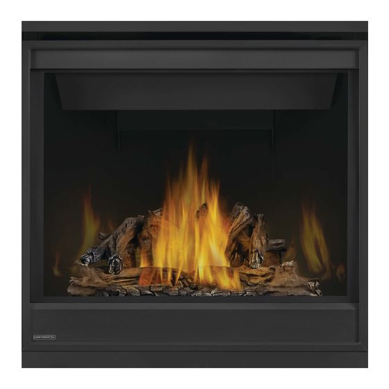
Product Name / Code
Builder Series X 36
NATURAL GAS MODELS: CX36NTREA-1
ADD ____ ILLUSTRATED
PROPANE GAS MODELS: CX36PTREA-1
CX36-1 ILLUSTRATED
FOR INDOOR USE ONLY
PLACE BARCODE LABEL ON THE
IF INSTALLATION + OPERATION,
ADD SERIAL NUMBER LABEL HERE.
OWNER'S MANUAL
LABEL ON THE OWNER'S MANUAL"
W415-3099 / B / 05.03.22
Advertisement
Table of Contents

Subscribe to Our Youtube Channel
Related Manuals for Continental Fireplaces MODELS X 36 Series


Summary of Contents for Continental Fireplaces MODELS X 36 Series
- Page 1 ENGLISH ADD MANUAL TITLE INSTALLATION AND SAFETY INFORMATION WARNING OPERATION MANUAL Product Name / Code FIRE OR EXPLOSION HAZARD (MUST use title from Price Book) Failure to follow safety warnings Builder Series X 36 exactly could result in serious NATURAL GAS MODELS: ADD PRODUCT CODE HERE injury, death, or property damage.
- Page 2 safety information WARNING DANGER • This appliance is hot when operated and can cause severe burns if contacted. • Any changes or alterations to this appliance or its controls can be dangerous and is prohibited. HOT GLASS WILL CAUSE • Do not operate appliance before reading and BURNS.
- Page 3 patterns. RAAK HET GLAS NIET AAN TOT HET IS AFGEKOELD. DUTCH safety information LAAT KINDEREN NOOIT HET GLAS AANRAKEN. WARNING Dit apparaat is voorzien van een barrière die is ontworpen om het risico van brandwonden door het hete kijkglas te beperken. Deze barrière moet worden geïnstalleerd ter bescherming van kinderen •...
-
Page 4: Table Of Contents
table of contents general information electrical information rates and efficiencies hard wiring connection installation overview wiring diagram rating plate information 5.4.1 wiring diagram (Dexen EI) mobile home installation 5.2.1 battery back-up installation operation dimensions venting requirements gas installation finish framing typical vent installation special vent installations minimum framing dimensions... -
Page 5: General Information
standard checklist Installer: please fill out appliance checklist in the Owner's manual. 1.0 general information When the appliance is installed at elevations above 4,500ft (1372m), and in the absence of specific recommendations from the local authority having jurisdiction, the certified high altitude input rating shall be reduced at the rate of 4% for each additional 1,000ft (305m). - Page 6 standard checklist installation overview Recommended installation steps: 1. Determine venting requirements before deciding the final location of the appliance. 2. Install rough framing (see “rough framing” section). 3. Place the appliance in its final position. 4. Install appliance venting (see “venting installation” section). 5.
- Page 7 general information WARNING • Always light the pilot whether for the first time or if the gas supply has run out, with the glass door opened or removed. • Provide adequate clearance for servicing and operating the appliance. • Provide adequate ventilation. •...
-
Page 8: Rating Plate Information
general information rating plate information Certified to Canadian and American National Standards: CSA 2.22-XXXX / ANSI Z21.50-XXXX for Vented Decorative Gas Appliances Certifié selon les normes Nationales Canadiennes et Américaines: CSA 2.22-XXXX / ANSI Z21.50-XXXX pour les Appareils à gaz décoratif à évacuation Direct vent, vented gas fireplaces. -
Page 9: Dimensions
general information dimensions W415-3099 / B / 05.03.22... - Page 10 2.0 venting requirements venting requirements WARNING • Risk of fi re. Maintain specifi ed air space clearances to vent pipe and appliance. • The vent system must be supported every 3’(0.9m) for both vertical and horizontal runs. Use support ring assembly W010- 0067 or equivalent non-combustible strapping to maintain the minimum clearance to combustibles for both vertical and horizontal runs.
-
Page 11: Venting Requirements
be combined. These vent kits allow for either horizontal or vertical venting of the appliance. The maximum allowable horizontal run is 20 venting requirements feet (6.1m). The maximum allowable vertical vent length is 40 feet (12.2m). The maximum number of vent connections is two horizontally or three vertically (excluding the appliance and the air terminal connections) when using fl exible venting. - Page 12 venting requirements 16" (40.6cm) minimum 40 ft (12m) Maximum 3 ft (1m) minimum 20" (50.8cm) Max. 24" (61cm) 24" minimum plus rise * (61cm) REAR VENT * See "venting" section W415-3099 / B / 05.03.22...
-
Page 13: Special Vent Installations
venting requirements special vent installations 2.2.1 periscope termination Use the periscope kit to locate the air termination above grade. The periscope must be installed so that when fi nal grading is completed, the bottom air slot is located a minimum 12” (305mm) above grade. The maximum allowable vent length (including both rise and run) is 10’... -
Page 14: Minimum Air Terminal Location Clearances
venting requirements minimum air terminal location clearances Covered balcony applications ††* = 3 feet ≤ 15 feet = 2 x ACTUAL (0.9m) (4.6m) note: INSTALLATIONS Wall terminals are for illustration purposes only. Size and shapes may vary. Wall terminal CANADA U.S.A. -
Page 15: Venting Application Flow Chart
venting requirements venting application flow chart TOP EXIT Horizontal Termination Vertical Termination Vertical rise is equal Vertical rise is equal Vertical rise is less Vertical rise is less to or greater than to or greater than than horizontal run than horizontal run the horizontal run the horizontal run Horizontal run +... -
Page 16: Elbow Vent Length Values
venting requirements elbow vent length values FEET INCHES MILLIMETERS 1° 0.03 12.7 15° 0.45 152.4 30° 11.0 279.4 45° 1.35 16.0 406.4 90°* 32.0 812.8 * The fi rst 90° offset has a zero value and is shown in the formula as - 90° top exit horizontal termination 15.1A ) <... - Page 17 venting requirements ) > (V Simple venting configuration See graph to determine the required vertical rise V for the required horizontal run H (only one 90° elbow) 150 (381) 147 (373) REQUIRED VERTICAL 100 (254) RISE IN INCHES (CENTIMETERS) V 57 (145) 50 (127) 8 (20.3)
-
Page 18: Rear Exit Horizontal Termination
venting requirements rear exit horizontal termination ) < (V Simple venting configuration See graph to determine the required vertical rise V for the required (only two 90° elbows) horizontal run H 40 (12.2) 35.3 (10.7) REQUIRED 30 (9.1) VERTICAL RISE IN 20 (6.1) FEET (METERS) V... - Page 19 venting requirements ) > (V Simple venting configuration See graph to determine the required vertical rise V for the (only two 90° elbows) required horizontal run H 12.5 (3.8) 12.25 (3.7) REQUIRED VERTICAL RISE IN 8.3 (2.54) FEET (METERS)V (1.68) 4.2 (1.3) (0.3) 12.5...
- Page 20 venting requirements top and rear exit vertical termination ) < (V See graph to determine the required vertical rise V for the Simple venting configurations. required horizontal run H 40 (12.2) 30 (9.1) REQUIRED VERTICAL RISE IN FEET 20 (6.1) (METERS)V 10 (3.1) 3 (0.9)
- Page 21 venting requirements ) > (V See graph to determine the required vertical rise V for the Simple venting configurations. required horizontal run H 20 (6.1) 19 (5.8) REQUIRED VERTICAL 10 (3.1) RISE IN FEET 3 (0.9) (METERS)V (1.5) (3.1) (4.6) (6.1) (7.6) (9.1)
-
Page 22: Rear Exit
venting requirements Example: = 1.5 FT (0.5m) = 5 FT (1.5m) = 1.5FT (0.5m)+ 5FT (1.5m) = 6.5 FT (2m) = 1 FT (0.3m) = 1 FT (0.3m) = 10.75 FT (3.3m) = 1FT (0.3m) + 1FT (0.3m) + 10.75FT (3.3m) = 12.75FT (3.9m) = .03 (three 90°... -
Page 23: Rear Exit Shield (For Rear Vent Only)
venting requirements 2.11 rear exit shield (for rear vent only) Remove the safety barrier assembly and door from the appliance, refer to the “safety barrier & door removal / installation” section of the manual for detailed instructions. Loosen the two screws, that secure the exhaust plate, and slide the shield in place by sliding its slotted openings behind the screwheads, tighten the two previously loosened screws. -
Page 24: Top Exit
venting requirements 2.12 top exit WARNING • Failure to install the cover plate and gasket will cause the appliance to function improperly and can cause injury or property damage. This appliance has been factory shipped as a rear vent. Remove the safety barrier and glass door (see "safety barrier & door removal/installation" section). FIG. - Page 25 3.0 rough framing rough framing note: When using optional fi nishing accessories, the framing dimensions and fi nishing materials may differ from what is outlined in the section below; refer to the leafl et instructions supplied in the accessory kit for specifi c framing and fi nishing specifi cations.
-
Page 26: Rough Framing
rough framing minimum framing dimensions 35 1/8” SIDE WALL (89.2cm) 2” (51mm) 35 1/2” (90.2cm) Do not put objects in front of the appliance (minimum distance of 4 feet) 16” (40.6cm) HORIZONTAL VENT SECTIONS: A minimum of 1" (25mm) at the bottom and sides, and 3" (76.2mm) at the top of the vent pipe on all horizontal runs to combustibles is required. -
Page 27: Minimum Enclosure Clearances
rough framing minimum enclosure clearances TOP VENT PLAFOND CEILING ENCLOSURE TOP EXIT ENCLOSURE The appliance requires a minimum enclosure height of 50 1/2" (128.3cm). For temperature requirements, the enclosure space around and above the appliance must be left unobstructed. NOTE: The vent shield is telescopic and must be adjusted to shield the full depth of the combustible wall penetration. - Page 28 rough framing MINIMUM REAR VENT CLEARANCES For rear vent termination not exceeding 10" (254mm) of horizontal vent run. Ceiling Plafon Enclosure 24" (61cm) REAR EXIT ENCLOSURE The appliance requires a minimum enclosure height of 44" (111.8cm). For temperature requirements, the enclosure space around and above the appliance must be left unobstructed.
- Page 29 rough framing MAXIMUM REAR VENT CLEARANCES (EXAMPLE 1: INTERIOR NICHE / BUMPOUT / ALCOVE) 24" (61cm) REAR EXIT ENCLOSURE The appliance requires a minimum enclosure height of 44" (111.8cm). For temperature requirements, the enclosure space around and above the appliance must be left unobstructed. NOTE: The vent shield is telescopic and must be adjusted to shield the full depth of the combustible wall penetration.
- Page 30 rough framing MAXIMUM REAR VENT CLEARANCES (EXAMPLE 2: EXTERIOR ALCOVE / DOGHOUSE) 24" (61cm) REAR EXIT ENCLOSURE The appliance requires a minimum enclosure height of 44" (111.8cm). For temperature requirements, the enclosure space around and above the appliance must be left unobstructed. NOTE: The vent shield is telescopic and must be adjusted to shield the full depth of the combustible wall penetration.
- Page 31 rough framing note: For heavier finishing materials such as marble, we recommend adding extra support to the frame. Ensure there is adequate floor support for the appliance and finishing material. Before framing your appliance, determine vent requirements before deciding the final location of the appliance. After rough framing, place the appliance in its final position.
-
Page 32: Venting Installation
venting installation 4.0 venting installation WARNING • Ensure to unpack all loose materials from inside the fi rebox prior to connecting the gas and electrical supply • If your appliance is supplied with a remote, ensure the remote receiver is in the “OFF” position prior to connecting the gas and electrical supply to the appliance. -
Page 33: Horizontal Installation
venting installation horizontal installation WARNING • The fi restop assembly must be installed with the vent shield to the top. • Terminals must not be recessed into a wall or siding more than the depth of the return fl ange of the mounting plate. -
Page 34: Vertical Installation
venting installation vertical installation This application occurs when venting through a roof. Installation kits for various roof pitches are available from your authorized dealer / distributor. See the “accessories” section to order specifi c kits required. A. Determine the air terminal location, cut and frame a square opening, as illustrated, in the ceiling and the roof to provide the minimum 1"... -
Page 35: Using Either Flexible Or Rigid Vent
venting installation using either flexible or rigid vent components WARNING • Do not allow the inner fl ex pipe to bunch up on horizontal or vertical runs and elbows. Keep it pulled tight. • Spacers are attached to the inner fl ex pipe at predetermined intervals to maintain an even air gap to the outer fl ex pipe. -
Page 36: Vertical Air Terminal Installation
venting installation 4.3.2 vertical air terminal installation WARNING • Maintain a minimum 2” (51mm) space between the air inlet base and the storm collar. note: Fastening hardware provided with appropriate roof terminal and liner kits. Fasten the roof support to the roof using 6 screws. The roof support is optional. -
Page 37: Horizontal Air Terminal Installation
venting installation 4.3.4 horizontal air terminal installation Move the appliance into position. Measure #10x2" the vent length required between terminal and SCREWS appliance taking into account the additional CAULKING length needed for the fi nished wall surface and any 2” (50.8mm) overlaps between venting INNER components. -
Page 38: Vertical Air Terminal Installation
venting installation 4.3.5 vertical air terminal installation WARNING • Maintain a minimum 2” (51mm) space between the air inlet base and the storm collar. note: Fastening hardware provided with appropriate roof terminal and liner kits. Before attaching elbows to the collars on the back of the appliance, 1 1/2” (38.1mm) will need to be trimmed off the 4”... -
Page 39: Vertical Through Existing Chimney
venting installation vertical through existing chimney WARNING • Risk of fi re. • Co-axial to co-linear venting confi gurations must only be used in a non-combustible chimney or enclosure. Installation in a combustible enclosure could result in a fi re. This appliance is designed to be attached to a 3”... -
Page 40: Restricting Vertical Vents
venting installation 4.4.1 restricting vertical vents WARNING • Turn off gas and electrical supply before servicing the appliance. • Appliance may be hot, do not service until appliance is cool. • For safe and proper operation of the appliance, follow the venting instruction exactly. •... -
Page 41: Electrical Information
5.0 electrical information electrical information hard wiring connection It is necessary to hard wire this appliance. This appliance must be electrically connected and grounded in accordance with local codes. In the absence of local codes, use the current CSA C22.1 Canadian Electrical Code in Canada or the ANSI/NFPA 70-1996 National Electrical Code in the United States. -
Page 42: Battery Back-Up Installation
electrical information 5.2.1 battery back-up installation WARNING • Ensure the gas and electrical power to the appliance is turned off. • Appliance may be hot. Do not service until the appliance has cooled. note: In the event of a power failure, your appliance can be operated using the supplied battery back-up. Remove the safety barrier to easily access the control compartment. -
Page 43: Operation
6.0 operation electrical information WARNING • If you do not follow these instructions exactly, a fi re or explosion may result causing property damage, personal injury, or loss of life. • If applicable, always light the pilot whether for the fi rst time or if the gas supply has run out with the glass door opened or removed. -
Page 44: Gas Installation
7.0 gas installation gas installation WARNING • Risk of fi re, explosion, or asphyxiation. Ensure there are no ignition sources such as sparks or open fl ames. • Support gas control when attaching gas supply pipe to prevent damaging gas line. •... -
Page 45: Finish Framing
8.0 finish framing finish framing minimum framing dimensions WARNING • Risk of fire! • Maintain all specified air space clearances to combustibles. Failure to comply with these instructions may cause a fire or cause the appliance to overheat. • Ensure all clearances (i.e. back, side, top, vent, mantel, front, etc.) are clearly maintained. 35"... -
Page 46: Finishing
finishing 9.0 finishing WARNING • Risk of fire! • Never obstruct the front opening of the appliance. • The front of the appliance must be finished with any non-combustible materials such as brick, marble, granite, etc., provided that these materials do not go below the specified dimension, as illustrated. •... -
Page 47: Front Hood Installation
finishing front hood installation note: This hood must be installed, if it has not already been factory installed. Safety door and screen must be removed. Remove the securing screws from the top of the firebox, as shown. Install the front hood, ensure it is angled downward when installed. Reinstall the previously removed securing screws. -
Page 48: Non-Combustible Facing Material
finishing non-combustible facing material WARNING Non-combustible facing material must not project more than 4” (101.6mm) from the face of the door (all four sides). If greater projections are desired, increase the clearance to the sides, bottom and top by 2” (50.8mm) for every additional 1”... -
Page 49: Minimum Mantel Clearances
finishing minimum mantel clearances WARNING • Risk of fi re. Maintain all specifi ed air space clearances to combustibles. Failure to comply with these instructions may cause a fi re or cause the appliance to overheat. Ensure all clearances (i.e. back, side, top, vent, mantel, front, etc.) are clearly maintained. -
Page 50: Recessed Installation
finishing recessed installation WARNING • Installing a television or other electronics above the appliance may cause discolouration, melting, or damage to the electronics. Use clearances as guidelines and refer to your TV manufacturer’s instructions for further information Image note: Recesses or alcoves above the appliance must be made with non-combustible material and regular minimum clearances, as defi ned for combustible materials, must still be applied. -
Page 51: Log Placement
more uniform as colour pigments burn in during the heat-activated curing process.” finishing Insert only if note: log placement applicable ----> Log numbers are located on the bottom or back of the logs. WARNING Log Number Part Number Description • Failure to position the logs in accordance with these diagrams or failure to use only logs specifi cally approved with this appliance may result in property damage or personal injury. - Page 52 Stud (Log #3) Stud (Log #3) Studs (Log #4) Studs (Log #4) finishing Stud (Log #2) Stud (Log #2) Stud (Log #2) Stud (Log #2) Notch Notch Stud (Log #3) Stud (Log #3) Studs (Log #4) Studs (Log #4) Notch Notch Stud (Log #3) Stud (Log #3)
-
Page 53: Glowing Embers
NOTE: ENSURE NOMENCLATURE IS NOTE: ENSURE NOMENCLATURE IS CONSISTENT THROUGHOUT. CONSISTENT THROUGHOUT. finishing IF SPACE IS LEFT OVER, USE THIS BOX TO IF SPACE IS LEFT OVER, USE THIS BOX TO SHOW CORRECT FINAL LOG PLACEMENT SHOW CORRECT FINAL LOG WITH LINE DRAWINGS. -
Page 54: Optional Blower Installation
10.0 optional blower installation finishing WARNING • Ensure the appliance is completely cool before starting installation. • To avoid danger of suffocation, keep the packaging bag away from babies and children. Do not use in cribs, aub - aSCent univerSal blower inStallation inStruCtionS beds, carriages, or play pens. -
Page 55: Adjustments
(12.7mm - 9.5mm) of thermocouple 11.0 adjustments adjustment 11.1 check pressure readings Adjust the pilot screw to provide properly sized fl ame. Turn in a clockwise direction to reduce the gas fl ow. SIT ELECTRONIC IGNITION Check Pressure Readings: Inlet pressure can be checked by turning screw (A) counter- clockwise 2 or 3 turns and then placing pressure gauge tubing 3/8”... -
Page 56: Venturi Adjustment
ODS - MILLIVOLT adjustment 11.2 venturi adjustment This appliance has an air shutter that has been factory set open according to the chart below: VENTURI Regardless of venturi orientation, closing the air shutter will cause a more BURNER yellow flame, but can lead to carbonization. Opening the air shutter will cause a more blue flame, but can cause flame lifting from the burner ports. -
Page 57: Annual Maintenance
12.0 maintenance maintenance WARNING • Turn off the gas and electrical power before servicing the appliance. • Appliance may be hot. Do not service until appliance has cooled. • Do not use abrasive cleaners on glass. • Do not paint the pilot assembly. This appliance and its venting system should be inspected before use and at least annually by a qualifi ed service person. -
Page 58: Door Glass Replacement
• Using a vacuum with soft brush attachment, gently remove any dirt, debris, or carbon build up from the logs, fi rebox, and burner. For glass media, follow the installation instructions for pre-cleaning. • Gently remove any build-up on the pilot assembly including thermopile, thermocouple, fl ame sensor, and maintenance igniter (if equipped). -
Page 59: Replacement Parts
replacement parts 13.0 replacement parts WARNING • Failure to position the parts in accordance with this manual or failure to use only parts specifi cally approved with this appliance may result in property damage or personal injury. • **This is a fast acting thermocouple. It is an integral safety component. Replace only with a fast acting supplied by Wolf Steel Ltd. -
Page 60: Overview
replacement parts W415-3099 / B / 05.03.22... -
Page 61: Valve Train Assembly
replacement parts W415-3099 / B / 05.03.22... -
Page 62: Troubleshooting
14.0 troubleshooting troubleshooting WARNING • Always light the pilot whether for the fi rst time or if the gas supply has run out, with the glass door open or removed. • Turn off gas and electrical power before servicing the appliance. •... - Page 63 Check that venting is installed correctly. appliances). Room is in negative pressure; increase fresh air supply. troubleshooting symptom problem test solution Pilot will not light. Makes Wiring: short, loose, or damaged Verify the thermocouple/sensor is clean and the wiring is undamaged. Verify the interrupter block is not damaged or too tight.
- Page 64 Wire connector pins are bent. Straighten pins. Valve wiring is damaged. Replace valve. troubleshooting symptom problem test solution Lights or blower Control module switch in Verify ON/OFF switch is in the “I” position which denotes on. won’t function (if wrong position. equipped).
-
Page 65: Warranty
warranty 15.0 warranty Continental® products are manufactured under the strict standard of the world recognized ISO 9001 : 2015 Quality Management System. Continental® products are designed with superior components and materials assembled by trained craftsmen who take great pride in their work. The burner and valve assembly are leak and test-fi red at a quality test station. The complete appliance is again thoroughly inspected by a qualifi ed technician before packaging to ensure that you, the customer, receives the quality product that you expect from Continental®. -
Page 66: Service History
warranty 16.0 service history W415-3099 / B / 05.03.22... - Page 67 notes 29.1 W415-3099 / B / 05.03.22...
Need help?
Do you have a question about the MODELS X 36 Series and is the answer not in the manual?
Questions and answers