
Related Manuals for Husqvarna VIKING HUSKYLOCK 936


Summary of Contents for Husqvarna VIKING HUSKYLOCK 936
- Page 1 SERVICE MANUAL HUSKYLOCK MODEL 936 Made in Sweden 104 72 49-26 May 2005 (Rev D) (replaces 104 72 44-26)
-
Page 2: Table Of Contents
23. CHAIN STITCH LOOPER TAKE UP LEVER ...............27 24. STITCH LENGTH ........................28 25. DIFFERENTIAL FEEDING ....................29 26. THREAD TENSION .......................30 27. PRESSERFOOT HEIGHT .....................31 Wiring diagram .........................32 Fault finding diagram- mechanically ..................35 Fault finding diagram - Electronically ..................39 2 Husqvarna Viking Huskylock 936 104 72 49-26... - Page 3 Ref. No 412 38 85-01 3. Allen key 2.5 mm Ref. No 411 86 01-01 4.Allen Key 2 mm Ref. No 411 86 00-01 5.Allen Key 1,5 mm Ref. No 411 66 89-01 104 72 49-26 Husqvarna Viking Huskylock 936...
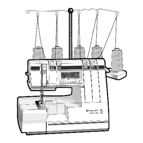
- Page 4 Sewing surface, flat bed cover Cutting width / stich width adjusting dial Cutter cover Front panel Front cover Handwheel Sewing advisior liquid crystal display (LCD) Stitch finger Upper cutter Stitch finger lever Stitch plate 4 Husqvarna Viking Huskylock 936 104 72 49-26...
-
Page 5: General Dismounting
9. Remove screws (M,N) and dismount the front cover. NOTE ! Set the needle in its lowest position. 10. Remove the cable from the circuit board on the front cover. 11. Mounting in reverse order. 104 72 49-26 Husqvarna Viking Huskylock 936... -
Page 6: Basic Setting For Cams
D = First cams second calibration mark. E = Second cams first calibration mark. F = Second cams second calibration mark. G = Third cams first calibration mark. H = Third cams second calibration mark. Front 6 Husqvarna Viking Huskylock 936 104 72 49-26... -
Page 7: Needle Height
2. HEIGHT OF LOWER LOOPER Check The distance (A) should be 68.5 + 0.2mm Adjustment Loosen screw (B) and adjust the height of the looper. 104 72 49-26 Husqvarna Viking Huskylock 936... -
Page 8: Clearance Between Lower Looper And Needles
0 - 0.03 mm. 3. Tighten screw. B = Lower looper C= Lower looper stand Note! If The Needle guard setting ATTENTION! If needle bar is twisted, clearance between lower looper and needles may differ. 8 Husqvarna Viking Huskylock 936 104 72 49-26... -
Page 9: End Position Of Lower Looper - Setting Of
2. Loosen screws of the lever (A) of the lower looper. Adjust distance between left side of the needle and the piont of the lower looper to 3.0 ± 0.2 mm. 3. Tighten screws. B = Lower looper 104 72 49-26 Husqvarna Viking Huskylock 936... -
Page 10: Clearance Between Needles Support And Needle - Needles (C) And (D)
1.Loosen screws (O) of the needle support and turn it until its clearance (M) to the needle is between 0-0.10 mm. 2. Tighten screw (O). K= Front needle support. L= Rear needle support. 10 Husqvarna Viking Huskylock 936 104 72 49-26... -
Page 11: Position Of Upper Looper Clutch Exhange Body
1.Put the looper clutch in the S-position. 2. Loosen the 2 screw’s (C) and move the clutch assemblyuntil there is no play between exchange body (A) and looper link (B) and tighten the screws (C). C- Position S-Position 104 72 49-26 Husqvarna Viking Huskylock 936... -
Page 12: Setting Of Upper Looper Postion
2.Loosen screw (A) of the link arm of the upper looper lever (B) and adjust the looper so that the clearance between the point of the the upper looper and the left side of the (C) needle is 6.4 mm. 3.Tighten screw (A). 12 Husqvarna Viking Huskylock 936 104 72 49-26... -
Page 13: Timing Of Upper Looper And Lower Looper
3.8 mm. 3.Tighten the screws (B). N.B. That (G) is equal to the distance (H). C= Upper looper D= Lower looper F= Lower shaft 104 72 49-26 Husqvarna Viking Huskylock 936... -
Page 14: Clearance Between Upper Looper And Lower Looper
2. Loosen fixing screw (B) of the upper looper and adjust the clearance between upper looper and lower looper. (0 - 0.10 mm). 3. Tighten screw (B). C = Upper looper 14 Husqvarna Viking Huskylock 936 104 72 49-26... -
Page 15: Height Of Chain Stitch Looper
10. HEIGHT OF CHAIN STITCH LOOPER Check The distance B should be 64.5 + 0,4mm Adjustment Loosen screw (A) and adjust the height of the looper. 104 72 49-26 Husqvarna Viking Huskylock 936... -
Page 16: Clearence Between Double Chain Looper And Needle
2. Loosen screw (A) on the double chain looper and adjust clearance between needle and point of looper by moving the double chain looper until it is 0 - 0.3 mm. 3. Tighten the screw (A). 16 Husqvarna Viking Huskylock 936 104 72 49-26... -
Page 17: Timing Of Double Chain Looper Aginst The Needle
2. Loosen screws (A) on the lever of the double chain looper. Adjust distance between right side of the needle and the tip of the double chain looper to 3.0 ± 0.2 mm. 3. Tighten screws (A). 104 72 49-26 Husqvarna Viking Huskylock 936... -
Page 18: Clearance Between Needles Support And Needle - Needles (A),(B) And (E)
G = 0.05-0.1 mm 3. Tighten screw (H). F = Needle support J = Frame Note! On Ver 2 the Needle support is located on the Chain stitch looper 18 Husqvarna Viking Huskylock 936 104 72 49-26... -
Page 19: Clearance Between Feed Dog And Stitch Plate Sideways
(F). ADJUSTMENT- Differential feed dog 1. Loosen screw (B). 2. Adjust the distance between the feed dog and the stitch plate so that (E) is be equal to the distance (F). 104 72 49-26 Husqvarna Viking Huskylock 936... -
Page 20: Position Of Feed Dog Front To Back
Loosen the 2 screws (C) and adjust the distance between the feed dog and stitch plate so distance D and E is correct. Tighten the screws (C). Mount the Motor and the Termnial Box. 20 Husqvarna Viking Huskylock 936 104 72 49-26... -
Page 21: Feed Dog Height
1. Move feed dog to its highest position by turning the handwheel towards you. 2. Loosen screw (A) and turn screw (B) so that the rear feed dog is 1 ± 0.1 mm above the stitch plate. 3. Tighten screw (A). C = Stitch plate 104 72 49-26 Husqvarna Viking Huskylock 936... - Page 22 1. Move feed dog to its highest position by turning the handwheel towards you. 2. Loosen screw (D) and adjust so that the front feed dog (A) is 1.2 ± 0.1 mm above the stich plate (C). 3. Tighten screw (D). C = Stitch plate 22 Husqvarna Viking Huskylock 936 104 72 49-26...
-
Page 23: Positions Of Lower Knifes
1. The lower knife cutting edge (B) should be aligned with the surface of the stitch plate (A). ADJUSTMENT Loosen screw (C). Adjust so the lower knife cutting edge is aligned with the surface of the stitch plate. 104 72 49-26 Husqvarna Viking Huskylock 936... -
Page 24: Positions Of Upper Knifes
1. By turning handwheel towards you, move upper knife to its lowest position. 2. Loosen upper knife fixing screws (B). 3. Adjust position of upper knife downwards 1.7 mm from the utting edge of the lower knife. 4. Tighten the screws (B). 24 Husqvarna Viking Huskylock 936 104 72 49-26... -
Page 25: Belt Tension
ADJUSTMENT 1. Loosen the two nuts (A) 2. Adjust the speed sensor housing (B) up or down until the motor runs without stopping for the "Overload" message. 3. Tighten the nuts (A). 104 72 49-26 Husqvarna Viking Huskylock 936... -
Page 26: Setting Between Thread Take-Up And Upper / Lower Thread Guide
4. Adjust the distance between the thread guide (D) and the lower looper thread take-up (C) so it’s 61.7 mm. 5. Tighten the screw (A). NOTE ! Both upper and lower thread take-up is adjusted at the same time. 26 Husqvarna Viking Huskylock 936 104 72 49-26... -
Page 27: Chain Stitch Looper Take Up Lever
Chain stitch looper take up lever and base plate should be 42.9 + 0,3 mm. ADJUSTMENT Loosen screw (A) and adjust the height of the take up lever. B= 42.9 + 0.3 mm 104 72 49-26 Husqvarna Viking Huskylock 936... -
Page 28: Stitch Length
2.In order to get the starting point of step motor switch the machine off then on. 3.Set stitch length to 5.0 mm and differential feed ratio to 1.0. 4.Turn the adjusting screw (A). 5.Re-check. 28 Husqvarna Viking Huskylock 936 104 72 49-26... -
Page 29: Differential Feeding
2.In order to get the starting point of step motor switch the machine off then on. 3 Set stitch length to 5.0 mm and differential feed ratio to 1.0. 4. Turn the adjusting screw (A). 5 Re-check B= Worm wheel Back Front 104 72 49-26 Husqvarna Viking Huskylock 936... -
Page 30: Thread Tension
2. The basic setting may be adjusted by blocking the plate sheet at the edge of the tread tension dial by means of a small screw driver while moving the thread tension dial. Thread tension harder Thread tension looser 30 Husqvarna Viking Huskylock 936 104 72 49-26... -
Page 31: Presserfoot Height
1. Loosen the screw (A). 2. The presser bar height can now be adjusted up or down until the distance is 4.7 mm between the presser foot and the stitch plate. 3. Tighten the screw (A). 104 72 49-26 Husqvarna Viking Huskylock 936... -
Page 32: Wiring Diagram
Wiring diagram 32 Husqvarna Viking Huskylock 936 104 72 49-26... - Page 33 Wiring diagram 104 72 49-26 Husqvarna Viking Huskylock 936...
- Page 34 Wiring diagram 34 Husqvarna Viking Huskylock 936 104 72 49-26...
-
Page 35: Fault Finding Diagram- Mechanically
Check or adjust the following settings 6. Timing of upper looper and lower looper 7. Clearance between upper looper and lower looper. The point of thelower looper has been broken - change looper 104 72 49-26 Husqvarna Viking Huskylock 936... - Page 36 13. Setting between thread take up and upperlooper thread guide 13. Setting between thread take up and lower looper thread guide 6. Timing of upper looper and lower looper. 7. Clearance between upper looper and lower looper. 36 Husqvarna Viking Huskylock 936 104 72 49-26...
- Page 37 Check or adjust the following settings 9. Feed dog height Stitch plate isn’t damaged. Presser foot isn’t damaged. 10. Position of upper / lower knife 10. Fabric is shrinking 104 72 49-26 Husqvarna Viking Huskylock 936...
- Page 38 Check or adjust the following settings 10. Position of upper / lower knife The upper knife isn’t damaged - change knife The lower knife isn’t damaged - change knife 38 Husqvarna Viking Huskylock 936 104 72 49-26...
-
Page 39: Fault Finding Diagram - Electronically
After steps on foot controller, machine runs, but with unstable revolution or sometimes stops. Remove speed sensor board, check if disc is broken or not: — If abnormal, change disc. — If normal, change speed sensor. — If still abnormal, change control board. 104 72 49-26 Husqvarna Viking Huskylock 936... - Page 40 (2)Machine does not run with closed cover, and indicates ”Close front cover" — Regulate the position of the switch. — If defective cover switch, change cover switch BUZZER Buzzer does not sound. — Change control board. 40 Husqvarna Viking Huskylock 936 104 72 49-26...
- Page 41 — Change power supply cord. — Measure the voltage of CN2, if abnormal change power switch assembly — Measure the voltage on CN4, if abnormal change power board — Change transformer. — Change control board. 104 72 49-26 Husqvarna Viking Huskylock 936...
- Page 42 Parts List Huskylock 936 104 22 64-96 (Replaces 104 22 27-96)
- Page 43 Husqvarna Huskylock 936 104 22 64 -96...
- Page 44 2150003-553 Lower shaft bushing 2141012-116 Thread guide (F) 2141002-149 Thread giude (F) holder 90206 Position decided bal 1650004-424 Position decided spring 60167 Washer 2141001-153 Swallow rubber foot 2141001-122 Set pin for swallow rubber foot 104 22 64-96 Husqvarna Huskylock 936...
- Page 45 Husqvarna Huskylock 936 104 22 64 -96...
- Page 46 Screw 416 10 47-01 LCD operating button 416 10 48-01 Speed change button 2143008-216 LCD protecting plate 2150008-710 LCD indicating plate 2143008-213 Printing electric board 11203 Tapping screw 416 10 50-01 LCD operating sticker 104 22 64-96 Husqvarna Huskylock 936...
- Page 47 Husqvarna Huskylock 936 104 22 64 -96...
- Page 48 Spring ring 2141002-378 Presser bar bracket stopper 10941 Set screw 40106 E Ring 2141002-543 Presserbar lifter stopper 10124 Set screw 2141002-541 Presser foot lifter cam 2141002-377-651 Pressure adjusting dial 2141002-584 Pressure adjusting stud 60113 Washer 104 22 64-96 Husqvarna Huskylock 936...
- Page 49 Husqvarna Huskylock 936 104 22 64 -96...
- Page 50 ( for needle clamp) 20309 Screw ( for needle holder) 10953 Screw ( for needle clamp cover) 2150002-340 Needle clamp ass’y 2150002-500 Needle bar ass’y 2141003-101 Upper shaft ass’y 2150002-230 Needle clamp sub assy’ 104 22 64-96 Husqvarna Huskylock 936...
- Page 51 Husqvarna Huskylock 936 104 22 64 -96...
- Page 52 10976 Set screw 2150004-133 Feed reglulator stand 10134 Set screw 30403 Adjusting nut 10964 Set screw 2150002-616 Chain stitch looper for assistant take-up cam 416 11 00-01 Set screw 416 11 11-01 Handwheel bush 104 22 64-96 Husqvarna Huskylock 936...
- Page 53 Husqvarna Huskylock 936 104 22 64 -96...
- Page 54 2154013-486 Chain stich looper thread guide 2150003-487 Spring cover 2150003-488 Spring 11055 Screw 40110 E-ring 60513 Washer 415 52 51-01 Washer 60107 Washer 20308 Screw ( from #389612) 2150002-509-C Needle guide ass’y (from #389612) 104 22 64-96 Husqvarna Huskylock 936...
- Page 55 Husqvarna Huskylock 936 104 22 64 -96...
- Page 56 Lower cutter stand ass’y ( from #389612) 11934 Screw 2141004-423 Dial shaft bushing 2141004-431 Cutting-width adjusting cam 1650004-696 Set screw 1650004-424 Position decided spring 90206 Position decided ball 2141004-422 Cutting-width adjusting dial bushing 60103 Washer 10146 Screw 104 22 64-96 Husqvarna Huskylock 936...
- Page 57 Husqvarna Huskylock 936 104 22 64 -96...
- Page 58 10132 Set screw 2141001-657 Differential feed shaft collar (2) 10135 Set screw 2150004-687 Differential feed shaft 416 01 55-01 Differential feed shaft collar 10135 Set screw 40106 E-Ring 2150004-287 Feed cam 10124 Set screw 104 22 64-96 Husqvarna Huskylock 936...
- Page 59 Husqvarna Huskylock 936 104 22 64 -96...
- Page 60 Terminal box 2144518-870 Switch ass’y (230-240 volt) 2144508-870 switch ass’y (120 volt) 2150008-836 Power supply plate 10964 Set screw 2144508-903 Repeating connector ass’y 2150008-837 End of controller 10986 Screw 2150008-846 Termial box holder plate 104 22 64-96 Husqvarna Huskylock 936...
- Page 61 Husqvarna Huskylock 936 104 22 64 -96...
- Page 62 10981 Screw 2141008-882 Switch button spring 2141008-883 Switch button 2150008-827 Switch cover 10985 Screw 412 31 44-01 Cable, standard 412 31 44-02 Cable USA, Can 412 15 98-01 Spring 412 31 89-01 Control unit 104 22 64-96 Husqvarna Huskylock 936...
- Page 63 Husqvarna Huskylock 936 104 22 64 -96...
- Page 64 412 53 31-36 Instruction book - Dutch 412 53 31-41 Instruction book - Ita 412 53 31-46 Instruction book - Spa 412 53 31-51 Instruction book - Ger 412 53 31-56 Instruction book - Russian 104 22 64-96 Husqvarna Huskylock 936...
Need help?
Do you have a question about the VIKING HUSKYLOCK 936 and is the answer not in the manual?
Questions and answers
The hand wheel will is extremely tight. The belt seems to be in good shape. Do the cams need to be oiled?
The needle housing is stuck in the down position and I cannot get it to raise. I cannot turn manually either.
To fix a stuck needle housing on a Husqvarna Viking Huskylock 936 that won't raise, follow these steps:
1. Check for Obstructions – Make sure no thread, lint, or fabric is blocking the movement of the needle housing. Clean the area if necessary.
2. Inspect the Needle – Ensure the needle is correctly installed, not bent, and is the recommended SCHMETZ 130/705 H type.
3. Check Needle Height Setting – Refer to the service manual to verify and adjust the needle height if necessary.
4. Examine Looper Clearance – Ensure the clearance between the lower looper and needle is correct, as improper settings can cause jamming.
5. Dismount Covers if Needed – Remove the support bed, free arm, and side covers following the manual instructions to access internal components.
6. Lubricate Moving Parts – Apply sewing machine oil to any stiff moving parts to reduce friction.
7. Manually Rotate the Handwheel – Carefully turn the handwheel to check if the needle housing moves freely. Avoid forcing it.
8. Check Timing of Loopers – If the timing between the upper and lower loopers is incorrect, adjustments may be required.
If the issue persists, refer to the service manual for mechanical fault-finding or seek professional servicing.
This answer is automatically generated