Table of Contents
Advertisement
Available languages
Available languages
Quick Links
IMPORTANT INSTRUCTIONS - OPERATING MANUAL
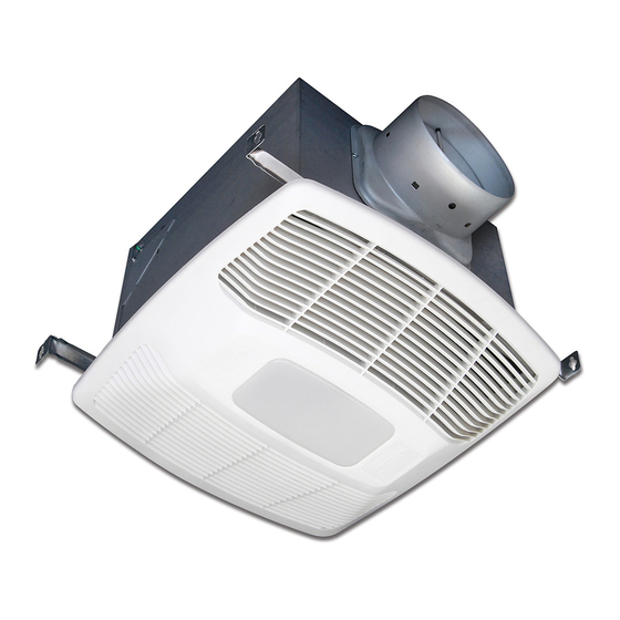
EVLD Series
READ AND SAVE THESE INSTRUCTIONS
READ CAREFULLY BEFORE ATTEMPTING TO ASSEMBLE, INSTALL, OPERATE OR MAINTAIN
THE PRODUCT DESCRIBED. PROTECT YOURSELF AND OTHERS BY OBSERVING ALL SAFETY
INFORMATION. FAILURE TO COMPLY WITH INSTRUCTIONS COULD RESULT IN PERSONAL
When using electrical appliances, basic precautions should
always be followed to reduce the risk of fire, electric shock and
WARNING:
ELECTRIC SHOCK AND INJURY TO PERSON,
OBSERVE THE FOLLOWING:
a) Use this unit only in the manner intended by the manufacturer. If you have
questions, contact the manufacturer.
b) Before servicing or cleaning the unit, switch power off at service panel
and lock the service disconnecting means to prevent power from being
switched on accidentally. When the service disconnecting means
cannot be locked, securely fasten a prominent warning device, such as
a tag, to the service panel.
WARNING:
ELECTRIC SHOCK AND INJURY TO PERSON,
OBSERVE THE FOLLOWING:
a) Installation work and electrical wiring must be done by qualified person(s)
in accordance with all applicable codes and standards, including fire-
related construction.
b) Sufficient air is needed for proper combustion and exhausting of gases
through the flue (chimney) of fuel burning equipment to prevent back
drafting. Follow the heating equipment manufacturer's guideline and
safety standards such as those published by the National Fire Protection
Association (NFPA) and the American Society for Heating, Refrigeration,
and Air Conditioning Engineers (ASHRAE), and the local code authorities.
c) When cutting or drilling into wall or ceiling, do not damage electrical wiring
and other hidden utilities.
6727916 Rev. J 9/22
INJURY AND/OR PROPERTY DAMAGE!
RETAIN INSTRUCTIONS FOR FUTURE REFERENCE.
GENERAL SAFETY INFORMATION
injury to person, including the following:
TO REDUCE THE RISK OF FIRE,
TO REDUCE THE RISK OF FIRE,
SAVE THESE INSTRUCTIONS
CAUTION:
DO NOT USE TO EXHAUST HAZARDOUS OR EXPLOSIVE
MATERIALS AND VAPORS.
d) Ducted fans must always be vented to the outdoors.
e) If this unit is to be installed over a tub or shower, it must be marked as
appropriate for the application and be connected to a gfci (ground fault
circuit interrupter) – protected branch circuit.
f) Do not install in a ceiling with thermal insulation value greater than r40.
g) This unit must be grounded.
h) To avoid motor bearing damage and noisy and/or unbalanced impellers,
keep drywall spray, construction dust, etc. Off power unit.
i)
Read all instructions before installing or using exhaust fan.
WARNING:
WARNING:
OUTSIDE OF THE BUILDING HAS A STRONG EFFECT ON THE AIR
FLOW, NOISE AND ENERGY USE OF THE FAN. USE THE SHORTEST,
STRAIGHTEST DUCT ROUTING POSSIBLE FOR BEST PERFORMANCE, AND
AVOID INSTALLING THE FAN WITH SMALLER DUCTS THAN RECOMMENDED.
INSULATION AROUND THE DUCTS CAN REDUCE ENERGY LOSS AND
INHIBIT MOLD GROWTH. FANS INSTALLED WITH EXISTING DUCTS MAY
NOT ACHIEVE THEIR RATED AIRFLOW.
www.airkinglimited.com
Exhaust Fan with Light
FOR GENERAL VENTILATING USE ONLY.
WARNING:
TO REDUCE THE RISK OF FIRE,
ELECTRIC SHOCK, DO NOT USE THIS FAN WITH ANY
SOLID-STATE SPEED CONTROL DEVICE.
DO NOT USE IN KITCHENS.
THE DUCTING FROM THIS FAN TO THE
1 of 16
Advertisement
Table of Contents

Related Manuals for AirKing EVLD Series


Summary of Contents for AirKing EVLD Series
- Page 1 IMPORTANT INSTRUCTIONS - OPERATING MANUAL EVLD Series Exhaust Fan with Light READ AND SAVE THESE INSTRUCTIONS READ CAREFULLY BEFORE ATTEMPTING TO ASSEMBLE, INSTALL, OPERATE OR MAINTAIN THE PRODUCT DESCRIBED. PROTECT YOURSELF AND OTHERS BY OBSERVING ALL SAFETY INFORMATION. FAILURE TO COMPLY WITH INSTRUCTIONS COULD RESULT IN PERSONAL INJURY AND/OR PROPERTY DAMAGE! RETAIN INSTRUCTIONS FOR FUTURE REFERENCE.
- Page 2 SECTION 4 INSTALLATION INSTRUCTIONS Ducting CAUTION: MAKE SURE POWER IS SWITCHED OFF AT SERVICE NOTE: 6" OR LARGER RIGID DUCT IS RECOMMENDED FOR BEST PERFORMANCE. PANEL BEFORE STARTING INSTALLATION. CAUTION: SECTION 1 ALL DUCTING MUST COMPLY WITH LOCAL AND NATIONAL BUILDING CODES.
- Page 3 NOTE: There may be more than one white fan wire that will need to be connected to the white wire from the supply. Screw NOTE: The yellow wire may contain a wire crimp nut which will have to be cut off and the wire stripped. Motion Sensing Models Secure the electrical wires to the housing with an approved electrical connector.
-
Page 4: Rocker Switch
VARIABLE SPEED: First decide if you will require more or less than 65 CFM of ventilation Wire Compartment on the low speed setting. If it is less than 65 CFM place the Low CFM Range rocker switch on the 30-60 range. If it is more, place the low CFM range rocker switch on the 70-120 Black range. - Page 5 SECTION 10 Open the light lens on the grill by pushing into the lens and allowing in to spring open. Install the 8.5 watt LED (included) into the lamp holder by lining up the pins on the lamp Use and Care base to the socket of the lamp holder and turning the lamp body clockwise until the lamp snaps into place and is firmly seated in the lamp holder.
-
Page 6: Troubleshooting Guide
Troubleshooting Guide Trouble Probable Cause Suggested Remedy 1. Fan does not operate when the switch is on. A fuse may be blown or a circuit tripped. Replace fuse or reset circuit breaker. Connector plug from motor is not plugged in. 1b. Turn off power to unit. - Page 7 REPLACEMENT PARTS DIAGRAM All Models Qty. Description Replacement Part # Mounting Rails 5S1299002 6" Metal Collar Assembly 5S5299100 Grill Springs 5S1202046 Mounting Channel 5S1202123 Specific to Model EVLDH Blower Assembly 5S1239125 8.5 Watt LED 5S1299725 Qty. Description Replacement Part # Light Lens 5S1239116 Grill Assembly...
- Page 8 NOTES: www.airkinglimited.com 6727916 Rev. J 9/22 8 of 16...
- Page 9 INSTRUCTIONS IMPORTANTES – MANUEL D’OPÉRATION Ventilateur combiner, Série EVLD comprend lumière et ventilation LIRE ET CONSERVER CES INSTRUCTIONS LIRE SOIGNEUSEMENT AVANT DE TENTER D’ASSEMBLER, INSTALLER, OPÉRER OU DE RÉPARER LE PRODUIT DÉCRIT. PROTÉGEZ VOUS-MÊME ET LES AUTRES EN OBSERVANT TOUTE L’INFORMATION DE SÉCURITÉ. FAILLIR À SE CONFORMER AUX INSTRUCTIONS PEUT RÉSULTER EN BLESSURE PERSONNELLE GRAVE ET/OU EN DOMMAGE À...
- Page 10 SECTION 4 INSTRUCTIONS D’INSTALLATION Conduits ATTENTION : VOUS ASSURER QUE L’ALIMENTATION EST NOTE: UN CONDUIT PLUS RIGIDE DE 6 PO OU PLUS EST RECOMMANDE POUR UNE COUPÉE AU PANNEAU DE SERVICE AVANT DE COMMENCER L’INSTALLATION. MEILLEURE PERFORMANCE. SECTION 1 ATTENTION : TOUS LES CONDUITS DOIVENT ÊTRE CONFORMES Préparation du Ventilateur d’évacuation AUX CODES DU BÂTIMENT LOCAUX ET NATIONAUX.
- Page 11 REMARQUE : Il peut y avoir plus d’un fil blanc de ventilateur qui devra être relié au fil blanc de l’alimentation. REMARQUE : Le fil jaune peut contenir un écrou de fil à sertir qui devra être coupé et le fil dénudé. Modèles avec détection de mouvement Fixez les fils électriques au logement avec une prise électrique approuvée.
-
Page 12: Boutons De Réglage
VITESSE VARIABLE : Décidez d’abord si vous aurez besoin de plus ou de moins de 65 CFM Compartiment du fil de ventilation à vitesse lente. Si vous avez besoin de moins de 65 CFM, placez l’interrupteur à bascule de la limite inférieure de CFM sur une portée de 30-60. Si vous avez besoin de plus Noir de 65 CFM, placez l’interrupteur à... -
Page 13: Utilisation Et Entretien
SECTION 10 Ouvrez l’objectif de lumière sur la grille en poussant dans l’objectif pour lui permettre de s’ouvrir. Installez la LED de 8,5 watts (incluse) dans la douille en alignant les broches de la Utilisation et entretien base de la lampe à la prise de la douille de lampe. Tournez le corps de la lampe dans le sens horaire jusqu’à... -
Page 14: Guide De Dépannage
Guide de dépannage Trouble Cause Possible Solution Suggérée 1. Le ventilateur ne fonctionne pas lorsque 1a. Un fusible peut être grillé ou un disjoncteur Remplacer le fusible ou réinitialiser le disjoncteur. l’interrupteur est à la position en marche. peut être décle.nché. 1b. - Page 15 DIAGRAMME DES PIÈCES DE REMPLACEMENT Particularités de modèle EVLDH # de pièce de Qté. Description remplacement Assemblée de Grille 5S1250121 Assemblée du compartiment du fil 5S1250124 Bouton 5S1299802 Compartiment du capteur d’humidité 5S1239826 Particularités de modèle EVLDGH # de pièce de Qté.
- Page 16 REMARQUES: www.airkinglimited.com 6727916 Rev. J 9/22...
Need help?
Do you have a question about the EVLD Series and is the answer not in the manual?
Questions and answers