Advertisement
Quick Links
Advertisement

Subscribe to Our Youtube Channel
Related Manuals for Wise P980 Series


Summary of Contents for Wise P980 Series
- Page 1 Pressure Indicating Switch Manual P980 Series...
-
Page 2: Table Of Contents
01. INTRODUCTION 02. APPLICATION 03. FEATURES 04. SPECIFICATION AND STANDARDS 05. STRUCTURE AND FUNCTION 06. OPERATING PRINCIPLE 07. CONTACT POINT WORKING TYPE AND CONNECTION 08. HOW TO SET 09. USE 10. INSTALLATION 11. WIRING 12. GROUND 13. MAINTENANCE AND PRECAUTIONS... - Page 3 Instructions for Proper and Safe Operation For the right use and safety of this product, please read through this manual prior to use. Handling error may cause device trip, injury, or disaster. ■ WARNING Do not impose excessive pressure beyond the allowance. Do not use corrosive measuring fluid.
-
Page 4: Introduction
1. Introduction This product is a pressure-resistant explosion-proof contact pressure gauge with a built-in indicator and micro switch or inductive contact switch. Before you use this product, please read through this manual for correct use of each device. 2. Application On reaching a set pressure, this product can be used for process control, abnormality notice, or warning on the basis of the On/Off signal. - Page 5 7) Electrical Properties * Micro Contact Type Rated Voltage SIZE Withstand Voltage Insulation Resistance Resistance Load Inductive Load 125V AC 5A 125V AC 3A 100MΩ or 1500V AC, 50/60Hz 250V AC 3A 250V AC 2A more on 500VDC One Minute 100 mm (Between Each Terminal 30V DC 4A...
- Page 6 Measuring Pressure Range and Folded Terminal Gap DEAD BAND OVER RANGE ADJUSTABLE SETTING RANGE ONE SPDT TWO SPDT SET POINT SET POINT PROOF RANGE O (bar) -100 1000 -1~1 -100~100 Within 5 % of Within 10 % of 150 % of -1~1.6 -100~160 Adjustable Range...
-
Page 7: Structure And Function
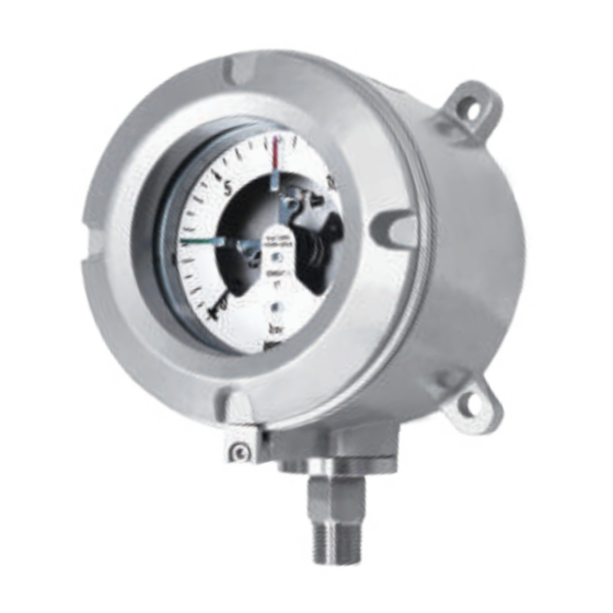
5. Structure and Function 100 mm Type Contact Part Pressure Indicator P981 MICRO CONTACT TYPE P982 ELECTRICAL CONTACT TYPE Description Description Description CASE BOURDON TUBE ELECTRICAL SWITCH COVER SHANK SCALE PLATE SAFETY GLASS POINTER CABLE GLAND ADJUST POINTER ORIFICE STOPER O-RING BOLT LOCK... -
Page 8: Operating Principle
6. Operating Principle 1. Pull Rod 2. Pull Rod Control Point 3. Toothed Segment 4. Segment Opening 5. Spiral Spring 6. Pointer When pressure is applied to the Bourdon Tube, it extends vertically. This vertical movement of Bourdon Tube is delivered to the Movement, and the Movement changes this vertical movement. -
Page 9: Contact Point Working Type And Connection
7. Contact Point Working Type and Connection Upper Limit Contact Type (HIGH ALARM) There is one contact point to turn the circuit ON if the pressure is above the setting or OFF if it is below the setting. * Micro Contact Type CONNECTION BOX MICRO SWITCH SET POINT... - Page 10 Lower Limit Contact Type (LOW ALARM) There is one contact point to turn the circuit ON if the pressure is below the setting or OFF if it is above the setting. * Micro Contact Type CONNECTION BOX MICRO SWITCH SET POINT Max.
- Page 11 Upper and lower limits contacts type (HIGH & LOW ALARM) There are two contacts in combination of two previously mentioned types. They operate independently of each other. * Micro Contact Type HIGH CONTACT (BLACK POINTER) CONNECTION BOX MICRO SWITCH CONNECTION TERMINAL LOW CONTACT (RED POINTER) CONNECTION TERMINAL SET POINT...
- Page 12 Two Upper Limit Contacts (HIGH & HIHIGH ALARM) There are two contacts combining two upper limit contact types that operate independently. * Micro Contact Type HIHIGH CONTACT (BLACK POINTER) CONNECTION BOX MICRO SWITCH CONNECTION TERMINAL HIGH CONTACT (RED POINTER) CONNECTION TERMINAL SET POINT Max.
- Page 13 Two Lower Limit Contacts (LOW & LOLOW ALARM) There are two contacts in combination of two lower limit contact types that operate independently. * Micro Contact Type LOW CONTACT (BLACK POINTER) CONNECTION BOX MICRO SWITCH CONNECTION TERMINAL LOLOW CONTACT (RED POINTER) CONNECTION TERMINAL SET POINT Max.
- Page 14 * Micro Contact Type - Wiring Diagram Micro switch Switch1 Switch2 ONE SPDT 1 (BROWN) 2 (GREEN / YELLOW) 3 (BLUE) 1 (RED) 2 (BLACK) 3 (GREEN) TWO SPDT 4 (YELLOW) 5 (WHITE) 6 (BLUE) ONE SPDT TWO SPDT When the input pressure reach the upper or lower limit set point. When the input pressure reach the upper or lower limit set point.
- Page 15 * Electrical Contact Type - Contact Function Table Contact function Wiebrock CABLE IDENTIFICATION Code Wiring scheme Slot sensor code no. contact contact EARTH CONTACT FUNCTION BROWN BLACK BLUE GREEN Contact make when Normal use pointer reachse setpoint high alarm (Normal open - NO) system Contact break when Normal use...
- Page 16 8. How to Set Use a screw driver to turn the adjustment shaft installed inside. Settings are shown below according to contact types. * Micro Switch Type Upper Limit Type (H) It will be turned ON if the pressure on the rise reaches the set value of the indicator hand. Adjust with the indicator hand to a new setting by moving it from the upper limit to upper limit.
- Page 17 9. Use When installing a gauge for the first time, it is recommended to use the valve so it can be removed or controlled easlily. It is required to find out followings before using the gauge. Before using the gauge, make sure zero point is properly adjusted. On the connection screw, use teflon tape or gasket to install the gauge firmly.
- Page 18 12. Ground The grounding terminal is made of aluminum to prevent corrosion. The ground bolt is made of 304SS. Spring washers are used to prevent loosening of the grounding terminal. Since the grounding terminal of the product uses O type, connect it accordingly. The outer diameter of the external grounding terminal is 4sq.
- Page 20 Pressure Indicating Switch Manual P980 Series...
- Page 21 한국어 01. 개요 02. 용도 03. 특징 04. 사양 및 규격 05. 각 부의 명칭과 기능 06. 동작원리 07. 접점 작동에 따른 종류 및 결선 08. 설정방법 09. 사용방법 10. 설치방법 11. 배선 12. 접지 13. 보수 및 사용상 주의사항...
- Page 22 한국어 바르고 안전한 사용을 위한 취급 설명서 이 제품을 바르고 안전하게 사용하기 위하여 사용 전에 이 취급 설명서를 잘 읽어주시기를 바랍니다. 취급 시의 오류는 기기고장의 원인이 되며, 상해나 사고 등의 재해가 발생할 수 있습니다. ■ 경고 압력 범위를 초과하는 압력을 가하지 마십시오. 부식성이...
- Page 23 한국어 1. 개요 본 제품은 지시계와 마이크로 스위치 또는 유도 접접 스위치가 내장되어 이을 조합한 내압 방폭형 접점부 압력계입니다. 본 제품을 사용하고자 할 경우 각각의 취급요령을 기재한 본 취급설명서를 숙지하시고 바르게 사용하여 주시기 바랍니다. 2. 용도 본 제품은 설정된 압력에 도달하였을 때 온, 오프(ON-OFF) 신호에 따른 프로세스 제어, 이상 경보 또는 경고등의 표시에 사용할 수 있습니다. 또한...
- Page 24 한국어 7) 주요사양 * Micro Contact Type 정격전류 SIZE 내전압 절연저항 저항부하 유도부하 125V AC 5A 125V AC 3A 500V DC 인가시 250V AC 3A 250V AC 2A 1500V AC 1분간 100 mm 100MΩ 이상 (케이스와 단자 간) 30V DC 4A 30V DC 3A (케이스와...
- Page 25 한국어 측정압력범위 및 접단차 DEAD BAND OVER RANGE ADJUSTABLE SETTING RANGE ONE SPDT TWO SPDT SET POINT SET POINT PROOF RANGE O (bar) -100 1000 -1~1 -100~100 Within 5 % of Within 10 % of 150 % of -1~1.6 -100~160 Adjustable Range Adjustable Range Adjustable Range...
- Page 26 한국어 5. 각 부의 명칭과 기능 100 mm형 접점 부 압력지시계 P981 MICRO CONTACT TYPE P982 ELECTRICAL CONTACT TYPE 번호 명칭 번호 명칭 번호 명칭 CASE BOURDON TUBE ELECTRICAL SWITCH COVER SHANK SCALE PLATE SAFETY GLASS POINTER CABLE GLAND ADJUST POINTER ORIFICE STOPER O-RING...
- Page 27 한국어 6. 동작 원리 1. 풀 로드( Pull Rod ) 2. 조정자( Pull Rod Control Point ) 3. 섹터( Toothed Segment ) 4. 섹터조정구간( Segment Opening ) 5. 실 태엽( Spiral Spring ) 6. 지시침( Pointer ) 부르돈관은 압력을 변위량으로 바꾸며 내기를 이용하여 크게 확대하고 회전으로 바꾼다. 내기는...
- Page 28 한국어 7. 접점 작동에 따른 종류 및 결선 상한 접점식( HIGH ALARM ) 1 접점으로 압력이 설정 압력 이상에 도달한 경우 회로를 온( ON )시키거나, 또는 압력이 설정 압력 이하에 도달하면 회로 오프( OFF ) 시킨다. * Micro Contact Type 단자대...
- Page 29 한국어 하한 접점식 ( LOW ALARM ) 1 접점으로 압력이 설정 압력 이하에 도달한 경우 회로를 온( ON )시키거나, 또는 압력이 설정 압력 이상에 도달하면 회로 오프( OFF ) 시킨다. * Micro Contact Type 단자대 마이크로 스위치 (CONNECTION BOX) (MICRO SWITCH) 설정치...
- Page 30 한국어 상하한 접점식 ( HIGH & LOW ALARM ) 2 접점 식으로 앞서 말한 상한 접점 식과 하한 접점 식을 조합한 것으로 각각 독립적으로 작동한다. * Micro Contact Type 단자대 마이크로 스위치 상한 접점(검정색침) 연결 단자 (HIGH CONTACT (BLACK POINTER) (CONNECTION BOX) (MICRO SWITCH) CONNECTION TERMINAL)
- Page 31 한국어 상한 2접점식 ( HIGH & HIHIGH ALARM ) 2 접점으로 상한 식을 두 개 조합한 것으로 각각 독립적으로 작동한다. * Micro Contact Type 단자대 마이크로 스위치 상한 접점(검정색침) 연결 단자 (HIHIGH CONTACT (BLACK POINTER) (CONNECTION BOX) (MICRO SWITCH) CONNECTION TERMINAL) 상한...
- Page 32 한국어 하한 2접점식 ( LOW & LOLOW ALARM ) 2 접점으로 하한 식을 두 개 조합한 것으로 각각 독립적으로 작동한다. * Micro Contact Type 단자대 마이크로 스위치 하한접점(검정색침) 연결단자 (LOW CONTACT (BLACK POINTER) (CONNECTION BOX) (MICRO SWITCH) CONNECTION TERMINAL) 하한접점(적색침) 연결단자 (LOLOW CONTACT (RED POINTER) 설정치...
- Page 33 한국어 * Micro Contact Type - Wiring Diagram Micro switch Switch1 Switch2 ONE SPDT 1 (BROWN) 2 (GREEN / YELLOW) 3 (BLUE) 1 (RED) 2 (BLACK) 3 (GREEN) TWO SPDT 4 (YELLOW) 5 (WHITE) 6 (BLUE) ONE SPDT TWO SPDT When the input pressure reach the upper or lower limit set point.
- Page 34 한국어 * Electrical Contact Type - Contact Function Table Contact function Wiebrock CABLE IDENTIFICATION Code Wiring scheme Slot sensor code no. contact contact EARTH CONTACT FUNCTION BROWN BLACK BLUE GREEN Contact make when Normal use pointer reachse setpoint high alarm (Normal open - NO) system Contact break when...
- Page 35 한국어 8. 설정 방법 설정은 내부에 설치된 조정축을 드라이버로 돌리면 된다. 접점 방식에 따라 아래에 설정 방법을 표시하였다. * Micro Switch Type 상한식 (H) 상승하는 압력이 설정 침의 지시하는 설정 점에 도달하였을 때 온 (ON) 된다. 설정 침을 설정 눈금의 고압 측에서 저압 측으로 이동하면서 설정 점에 맞춘다. 설정치...
- Page 36 한국어 9. 사용 방법 압력계를 최초 설치 시 밸브를 설치하여 분해하기 쉽도록 하십시오. 배관 라인의 진동 및 맥동 또는 온도가 있는지를 확인하여 필요시 악세서리를 설치 하십시오. 설치 하기 전 게이지의 0점이 맞는지 확인 하여 주십시오. 설치 시 나사에 테프론 테이프나 가스켓을 이용하여 견고하게 설치하여 주십시오. 설치가...
- Page 37 한국어 13. 보수 및 사용상 주의사항 상용압력은 최고 눈금의 75% 이하에서 사용하여 주십시오. 압력 범위를 초과하는 압력을 절대 가하지 마십시오. 급격한 가압, 감압을 피하십시오. 맥동압이나 충격압이 가할 염려가 있는 경우 댐프너 또는 게이지 프로텍터 등 과압방지 장치를 취부하여 주십시오. 압력계 내의 가동부에 주유하지 않도록 하십시오. 정기...
Need help?
Do you have a question about the P980 Series and is the answer not in the manual?
Questions and answers