Table of Contents
Advertisement
Quick Links
Advertisement
Table of Contents

Related Manuals for Wise P535


Summary of Contents for Wise P535
- Page 1 INSTRUCTION MANUAL ITEM : PRESSURE INDICATING SWITCH MODEL : P535, P536...
- Page 2 Instructions for proper and safe operation Please read instructions carefully prior to using the instrument for proper and safe operations. Mishandling could cause device malfunctions and result in disastrous injuries or accidents. WARNING 1. Do not exceed the pressure range allowed. 2.
-
Page 3: Table Of Contents
CONTENTS 1. INTRODUCTION 2. APPLICATIONS 3. FEATURES 4. SPECIFICATION AND STANDARDS 5. STRUCTURE AND FUNCTION 6. OPERATING PRINCIPLE 7. CONTACT POINT WORKING TYPE AND CONNECTION 8. HOW TO SET 9. MAINTENANCE AND OPERATION 10. USE 11. INSTALLATION 12. WIRING... -
Page 4: Introduction
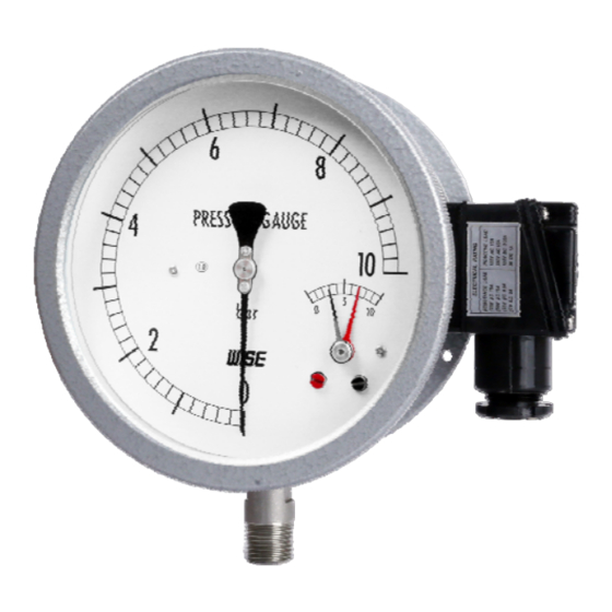
1. Introduction This is a contact switch pressure indicating with built-in indicator and micro switch. Please read the user manual carefully and thoroughly before using the product for proper and safe operations. 2. Applications The product can be used as an indicator to process control, error alarm or warning, in accordance with on or off signal if pressure reaches the predetermined setting. - Page 5 7) Electrical properties Rated voltage Withstand Insulation voltage resistance Resistance load Inductive load 125V AC 15A 125V AC 15A 1500V AC, 50/60Hz 100MΩ or more on 250V AC 15A 250V AC 15A one minute 500VDC ( Between each ( Between each 30V DC 30V DC 1A terminal and case )
-
Page 6: Structure And Function
5. Structure and Function Indicating type pressure switch( 100mm ) Indicating type pressure switch( 150mm ) 브르돈관 (BOURDON TUBE) 하우징 (HOUSING) 터미널 단자 (TERMINAL BLOCK) 마이크로스위치 (MICRO SWITCH) 내기 (MOVEMENT) 지시침 (POINTER) 설정침 (SET POINTER) -
Page 7: Operating Principle
6. Operating Principle As shown in diagram below, the bourdon tube transmits the position change according to pressure change through a lever to open or close the micro switch. 마이크로스위치 마이크로스위치 (MICRO SWITCH) (MICRO SWITCH) 브르돈관 로드 브르돈관 로드 (BOURDON TUBE) (BOURDON TUBE) (ROD) (ROD) -
Page 8: How To Set
3) Upper and lower limits contacts type (HIGH & LOW ALARM) There are two contacts in combination of two previously mentioned types. They operate independently of each other. 단자대 마이크로 스위치 (CONNECTION BOX) (MICRO SWITCH) 상한접점 (검정색침), 연결단자 (HIGH CONTACT (BLACK POINTER), 1 , 2 CONNECTION TERMINAL) 설정치... -
Page 9: Maintenance And Operation
1) Upper limit type (H) It will be turned ON if the pressure on the rise reaches the set value of the indicator hand. Adjust with the indicator hand to a new setting by moving it from the upper limit to lower limit. -
Page 10: Use
7) If the indication instrument makes a big error, remove it from the product for inspection. It may have been caused by wear, corrosion, external shock, vibration, or shock of a part. In this case, you must remove, adjust, or exchange the part. 8) The standard rated current shall follow 4. -
Page 11: Installation
11. Installation 1) Install in a place devoid of moisture, vibration, dust or corrosive gas. 2) Avoid areas that might exceed the temperature ranges specified in this manual. 3) Make sure to protect from lightning or steam. 4) Avoid areas with direct sun light. 5) Use M5 nuts and bolts to mount on a panel or wall using the mounting holes.
Need help?
Do you have a question about the P535 and is the answer not in the manual?
Questions and answers