Table of Contents
Advertisement
Quick Links
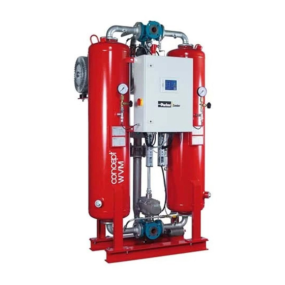
Adsorption dryer
WVM 45-1450
Visit: www.parker.com/wvm
Y
ONLINE AVAILABLE LANGUAGES:
EN:
Before the product installation, use the QR code
or visit the website to download the full user manual in
your language, See detailed instruction of this manual.
FR:
Avant l'installation du produit, utilisez le code QR
ou visitez le site pour télécharger le manuel d'utilisation
complet dans votre langue. Voir les instructions
détaillées de ce manuel.
( Generation - 5)
Operating manual
Y
IT
EN FR
DE NL
IT:
Prima di installare il prodotto, usa il QR code o
visita il sito per scaricarti il manuale completo nella tua
lingua. Vedi le istruzioni dettagliate di questo manuale.
DE:
Verwenden Sie vor der Produktinstallation den
QR-Code oder besuchen Sie die Website, um das
vollständige Benutzerhandbuch in Ihrer Sprache
herunterzuladen. Siehe ausführliche Anweisungen in
dieses Handbuchs..
14/02/2022 - rev 01 /EN
Cod: 398H271799
Advertisement
Table of Contents

Subscribe to Our Youtube Channel
Related Manuals for Parker WVM Series


Summary of Contents for Parker WVM Series
- Page 1 Adsorption dryer WVM 45-1450 ( Generation - 5) Operating manual Visit: www.parker.com/wvm EN FR DE NL ONLINE AVAILABLE LANGUAGES: Before the product installation, use the QR code Prima di installare il prodotto, usa il QR code o or visit the website to download the full user manual in visita il sito per scaricarti il manuale completo nella tua your language, See detailed instruction of this manual.
- Page 2 How to get your user manual Find the manual in your language Adsorption dryer WVM 45-1450 ( Generation - 5) Operating manual Visit: www.parker.com/wvm 04/02/2020 - rev 00 /EN Cod: 398H271799 EN FR DE NL ONLINE AVAILABLE LANGUAGES: Before the product installation, use the QR code...
-
Page 3: Table Of Contents
EN | Operating manual Index Machine Passport General information Manufacturer’s details ....................... 6 Dryer Specifi cations ........................6 About these operating instructions ................... 7 For your own safety Signs and danger zones at the dryer ..................8 Intended use of the dryer ......................10 General safety notes ....................... - Page 4 EN | Operating manual Notes on error messages and errors ..................48 Appendix: Technical Documents Technical data – overview of standard dryers ................. 50 Spare parts list ........................52 WVM 45 -1450...
-
Page 5: Machine Passport
EN | Operating manual Machine Passport Machine Passport Machine Type Order No. Catalogue No. Manufacture No. Vessel 1 No. Vessel 2 No. Date of Manufacture The operator is obliged to ◊ enter missing unit data in the above table, ◊ regularly update the unit data. The above device specifi cations are necessary to quickly identify the dryer and its compo- nents and facilitate servicing. -
Page 6: General Information
General information General information Manufacturer’s details Parker Hannifi n Manufacturing S.r.l. Sede Legale: Via Sebastiano Caboto 1, Palazzina “A” 20094 Corsico (MI) Italy Sede Operativa: Gas Separation and Filtration Division EMEA - Strada Zona Industriale, 4 35020 S.Angelo di Piove (PD) Italy tel +39 049 971 2111- fax +39 049 9701911 Web-site: www. -
Page 7: About These Operating Instructions
EN | Operating manual General information ◊ If the dryer is operated by personnel that does not have the requisite qualifi cations. ◊ If modifi cations are carried out on the dryer, and the manufacturer did not approve that. ◊ If notes given in pertaining operating manuals were not heeded. In the event of non-compliance the manufacturer will not accept any liability for any conse- quential damage whatsoever. -
Page 8: For Your Own Safety
EN | Operating manual For your own safety For your own safety The dryer has been built in accordance with the state of the art and the recognized technical safety regulations. Nevertheless, there is a risk of personal injury and damage to property when the dryer is used, if: ◊... - Page 9 EN | Operating manual For your own safety Danger zones at the dryer Risk of injury from hot vessel and Risk of injury by suddenly escaping gas piping surfaces Risks of injury by hot regeneration air Risk of injury by high voltage fl ow Risk of injury from crushing by shaft Risk of injury by blocked silencer...
-
Page 10: Intended Use Of The Dryer
EN | Operating manual For your own safety Intended use of the dryer The dryer is exclusively intended for drying compressed air. Depending on defi ned input conditions, it dries compressed air for industrial use. The dryer is designed for compressed air, which is free from aggressive water, oil, and solid matter constituents. -
Page 11: Safety Notes On Specifi C Operating Phases
EN | Operating manual For your own safety Safety notes on specifi c operating phases Transportation and siting ◊ Only use suitable and technically perfect lifting gear with a suffi cient carrying capacity. ◊ Carefully secure the dryer during transportation. Commissioning of the dryer Risk of injury from suddenly escaping gas! While the unit is under pressure, never remove any components or otherwise... - Page 12 EN | Operating manual For your own safety Servicing and troubleshooting the dryer Risk of injury from escaping compressed air! Never remove any parts of the dryer, or manipulate the same in any way, as long as the unit is pressurised! Suddenly escaping compressed air might cause serious injuries.
-
Page 13: Technical Product Description
EN | Operating manual Technical product description Technical product description Summary drawing Front view Main outlet valve l Control air fi lter and pressure reducer Charge sleeve for desiccant Dew point measuring chamber Electrical panel with operating panel Pressure build-up valve Pressure gauge - Pressure transducer Discharge sleeve for desiccant Vessel... - Page 14 EN | Operating manual Technical product description Rear view Lifting eye Aspiration of regeneration air Regenerating gas outlet temperature Heater (electrical resistance) sensor Regeneration air outlet Expansion valve with silencer Resistance thermometer for the control Vacuum pump temperature of the regeneration air Connector box of the heater (electrical resistance) with release button for the safety thermostat...
-
Page 15: Function
EN | Operating manual Technical product description Function The dryer dries the compressed air provided by the compressor and makes it available for industrial use. Upstream fi lters clean the compressed air and remove dust, dirt, oil, and water droplets, be- fore the compressed air reaches the dryer. - Page 16 EN | Operating manual Technical product description Regeneration (completed in parallel with adsorption) The regeneration is subdivided into four phas- The following fi gures show the regeneration phases (here: regeneration in right vessel) es: expansion, heating, cooling and pressure build-up. With the dewpoint-sensing control option, the regeneration phase is followed by a standby phase..
- Page 17 EN | Operating manual Technical product description Cooling phase (duration: approx. one hour) The hot, dried desiccant must now be cooled and is then ready for absorption. The heater is switched off so that the vacuum pump feeds cold ambient air through the vessel. If the “loop regeneration”...
-
Page 18: Options
EN | Operating manual Options Options The following options are available ◊ Pressure dewpoint control (included) ◊ Insulation and protection against contact (included) ◊ Adaptation for outdoor installation ◊ Auxiliary heating system, anti-freeze protection ◊ Intake fi lter for regeneration air ◊... - Page 19 EN | Operating manual Options The desiccant absorbs the moisture in the ambient air during the cooling phase. The amount of moisture taken in can be accordingly high at very high ambient temperatures and relative humidity (e.g. in tropical operating environments). A loop cooler can be implemented in order to prevent this situation and to ensure a stable pressure dewpoint under above mentioned adverse circumstances.
-
Page 20: Transportation, Installation And Storage
EN | Operating manual Transportation, installation and storage Transportation, installation and storage Danger due to incorrect transportation! The dryer must be transported by authorized and qualifi ed specialist personnel only. During transportation all applicable national regulations for accident pre- vention must be complied with. Otherwise there is a risk of personal injury. Warning! Always use the lifting eyes at the vessel top to lift the dryer. -
Page 21: Transporting Dryer To Its Location Of Installation
EN | Operating manual Transportation, installation and storage Transporting dryer to its location of installation Requirements regarding the location of installation The general conditions at the site of installation greatly affect the operation of the dryer and the service life of the desiccant. In order to ensure long-lasting operation with minimum main- tenance, the location of installation must meet the following requirements: Weather protection ◊... - Page 22 EN | Operating manual Transportation, installation and storage Installation base The installation base must be level, solid and free from vibration. It must be capable of bear- ing the dryer’s weight. You will fi nd the dryer’s weight in the technical data in the appendix. Please add another 10% to the dryer’s weight in your calculations.
- Page 23 EN | Operating manual Transportation, installation and storage Transporting of dryer Risk of serious injury due to improper transport! The dryer may only be transported by authorised and suitably qualifi ed techni- cal personnel. During transport, always comply with the applicable statutory safety regulations .
-
Page 24: Storage
EN | Operating manual Transportation, installation and storage Transport by crane Transport the adsorption dryer in an upright position to its location of installation. Transport by crane Transport by forklift When using a forklift, ensure that the dryer is always in an upright position. Secure the dryer with screws to a pallet to ensure that it cannot tilt or fall from the forklift. - Page 25 EN | Operating manual Transportation, installation and storage Note: To recommission the dryer after prolonged storage, please proceed as descri- bed for initial commissioning (see page 31). Store drying agents Do not store drying agents in the open air. Protect drying agents against humidity. WVM 45 -1450...
-
Page 26: Installation
EN | Operating manual Installation Installation Only authorized and qualifi ed specialist personnel may carry out work on pipes and electrical systems. The electrical panel in particular must be opened and serviced by an instructed trained electrician only As soon as the dryer has been set up at its installation location, you can install the com- pressed air infeed and outlet lines and make the electrical connections. - Page 27 EN | Operating manual Installation — In order to prevent corrosion in the pipes, we recommend the use of galvanised or stainless steel piping. — Provide a supporting fan in case of longer or widely branched pipelines and high differential pressures. Please contact the manufacturer for more information. —...
-
Page 28: Installation Of Pipelines
EN | Operating manual Installation Installation of pipelines To ensure proper operation of the dryer, its connection to the compressed air system must be free from stress. Prior to installation, check all incoming and outgoing compressed air lines and valves for damage or contamination. -
Page 29: Connection Of Electrical Components
EN | Operating manual Installation Connection of electrical components Beware of electrical voltage! Work on the electrical system must be entrusted to instructed, authorised elec- tricians only. The electrical panel in particular must be opened and serviced by an instructed trained electrician only. Connection to power supply The dryer components have been connected in the electrical panel at the factory. -
Page 30: Start-Up
EN | Operating manual Start-up Start-up Warning! The dryer must be taken into operation by trained personnel only! Untrained personnel does not have the required knowledge. Such personnel might cause serious faults. Note: You can order the initial commissioning and start-up from the manufacturer and have your personnel trained by the manufacturer. -
Page 31: Commissioning Of The Dryer
EN | Operating manual Start-up — must indicate a vacuum of 50 – 100 mbar during the drying phase. ◊ During the pressure build-up phase the indication on the pressure gauge should again rise to operating pressure level (both vessel gauges indicate the same operating pressure). Commissioning of the dryer Risk of injury from escaping hot regeneration air! Hot humid air might escape from the the regeneration air outlet at the vacuum... -
Page 32: Preparation For Commissioning
EN | Operating manual Start-up Preparation for commissioning For the commissioning of the dryer, follow the instructions as set out below. Pressurisation of unit Check the stop valves at the vessel pressure gauges to ensure that they are opened (see page 13). - Page 33 EN | Operating manual Start-up Inspecting direction of rotation of the vacuum pump Note: For the next steps, you will need an assistant. Ensure that the main switch is in position „0“ Open electrical panel door. Remove fuses of the heater (for location of the fuses see electrical diagram). This is necessary to ensure that the heater is not inadvertently switched on and thereby damaged.
- Page 34 EN | Operating manual Start-up Note: Checking can be facilitated for vacuum pumps starting up immediately (i.e. without star-delta circuit, see electrical diagram in the Appendix): Remove fuses of the heater. Turn on main switch. Briefl y actuate the contactor for the pump (see electrical diagram), e.g. with a screwdriver.
-
Page 35: Monitoring Dryer Operation
EN | Operating manual Monitoring dryer operation Monitoring dryer operation Notes on specifi c operating situations Parallel operation of several plants The standard confi guration comprises one compressor and one dryer. Please contact the manufacturer if you plan a plant differing from this confi guration. Part-load dryer operation The dryer provides optimum performance at high loads. -
Page 36: Shutdown And Restart Dryer
EN | Operating manual Shutdown and restart dryer Shutdown and restart dryer In the following cases, the dryer must be fully shut down and depressurised: ◊ In the event of an emergency or malfunction ◊ For maintenance work ◊ For dismantling Risk of injury from escaping compressed air! Never remove any parts of the dryer, or manipulate the same in any way, as long as the unit is pressurised! Suddenly escaping compressed air might cause... -
Page 37: Depressurising And Shutting Down The Dryer
EN | Operating manual Shutdown and restart dryer Depressurising and shutting down the dryer You must depressurise the dryer and shut it down for: ◊ maintenance ◊ disassembly Stop dryer (see the operating manual for the controller). Depending on the installed controller, the following stop situations can occur: ◊... -
Page 38: Restart
EN | Operating manual Shutdown and restart dryer Restart Restarting dryer: compressed air system and dryer under operating pressure If the dryer was shut off: switch on the dryer by setting the main switch to I. Otherwise: Start the dryer (see the operating manual for the controller). If necessary, slowly open the compressed air inlet and outlet valves installed by the operator. -
Page 39: Maintenance And Repair Of The Dryer
EN | Operating manual Maintenance and repair of the dryer Maintenance and repair of the dryer In order to allow maintenance work on the dryer to be carried out effi ciently and without dan- ger for maintenance personnel, you should comply with the following instructions. Notes on maintenance Warning! Maintenance tasks may be carried out only by authorized and qualifi... -
Page 40: Regular Maintenance Taskse
EN | Operating manual Maintenance and repair of the dryer Regular maintenance taskse The table below shows an overview of the regular maintenance tasks. The individual tasks are described in detail on the following pages. Component Maintenance task Maintenance interval Dryer Complete visual inspection and •... -
Page 41: Daily Maintenance Tasks
EN | Operating manual Maintenance and repair of the dryer Electric current warning! Work on the electric system must only be carried out by qualifi ed technical personnel! Cleaning Remove dust with dry cloth; use moist cloth, if necessary. Clean all surfaces, e.g. at the operating panel, with a moist cloth. Daily maintenance tasks Complete visual inspection and function test of the entire dryer Inspect dryer for visual damage and unusual noises. -
Page 42: Maintenance Interval (6 Months)
EN | Operating manual Maintenance and repair of the dryer Maintenance interval (6 months) Check the screw and clamp connections After six months at the latest, all the electrical panel’s screw and clamp connections must be checked to ensure that they are secure. The maintenance interval should be reduced in the case of a vibrating substrate or a vibrating compressor feed line. - Page 43 EN | Operating manual Maintenance and repair of the dryer Depressurise dryer and take out of service (see page 37). Remove the base of the fi lter. Remove fi lter element by turning it. Renew fi lter element. Mount the base of the fi lter. Dispose of spent fi lter element according to the statutory regulations.
-
Page 44: Maintenance Interval (24 Months)
EN | Operating manual Maintenance and repair of the dryer Take the new dewpoint sensor (2) from the box, remove the protective caps (4, 5) and screw it into the sensor chamber (3). Place seal onto sealing face; connect adapter (1) and secure it by tightening the screw. In case of misreading, check that the fl ow through the sensor is between 1 and 5 Nl/min. - Page 45 EN | Operating manual Maintenance and repair of the dryer Depressurise dryer and take out of service (see page 37). Unscrew fl ange and screw connections from the upper arch pipe system (see fi gure). Withdraw upper arch pipe complete with all mountings.
- Page 46 EN | Operating manual Maintenance and repair of the dryer Remove spent desiccant Release pressure from dryer and shut down the unit (see page 37). Place suitable container below the discharge sleeve. Remove the plug at the sleeve, using a suitable tool.
- Page 47 EN | Operating manual Maintenance and repair of the dryer Ensure that discharge sleeve is closed. Unscrew the plug of the fi lling hole with a suitable tool (see illustration). Slowly fi ll in new desiccant and make sure to heed the next step. Use a funnel if neces- sary.
-
Page 48: Identify And Eliminate Faults
EN | Operating manual Identify and eliminate faults Identify and eliminate faults The following table provides information on what designatory abbreviations are to be used for the various components. These designations are also found in the technical documentation. Abbreviation Component Fittings, general Butterfl y valve Check valve... - Page 49 EN | Operating manual Appendix: Technical Documents Appendix: Technical Documents The appendix of this operating manual contains the following technical documents and data: ◊ Technical data ◊ List of service and desiccant kits ◊ Process diagram ◊ Pneumatic diagram of the control air unit ◊...
- Page 50 EN | Operating manual Appendix: Technical Documents Technical data – overview of standard dryers Note: For dimensions and weight of the dryer refer to the enclosed dimensional drawing! Nominal capacity* TIPO m³/h m³/h mbar WVM 45 5,85 ~160 WVM 60 ~218 WVM 80 ~276...
- Page 51 EN | Operating manual Appendix: Technical Documents Note on load cycle calculation: According to the EC pressure equipment directive the dryers are rated for 14,000 load cycles. This corresponds to a service life of approx. 20 years when operated in the fi xed cycle of 6 hours (12 h total cycle time). 1 load cycle corre- sponds to the change from the unpressurised state to operating pressure.
- Page 52 EN | Operating manual Appendix: Technical Documents Spare parts list Note: When exchange or replacement parts are ordered, always state the dryer type and the build no. of the dryer. These data are found on the type plate. Service kits (wear parts kits, valid for 11 bar variants) Order no.
- Page 53 EN | Operating manual Appendix: Technical Documents Order no. For model Description GASKIT50W WVM 45-80 Flat gaskets DN50 GASKIT80W WVM 125-210 Flat gaskets DN80 GASKIT100W WVM 310-370 Flat gaskets DN100 GASKIT150W WVM 520-750 Flat gaskets DN150 GASKIT200W WVM 800-1080 Flat gaskets DN200 GASKIT250W WVM 1230-1450 Flat gaskets DN250...
- Page 54 EN | Operating manual Appendix: Technical Documents Desiccant packs* For model Order no. For model Order no. WVM 45 WVM45DESMIX WVM 520 WVM520DESMIX WVM 60 WVM60DESMIX WVM 615 WVM615DESMIX WVM 80 WVM80DESMIX WVM 750 WVM750DESMIX WVM 125 WVM125DESMIX WVM 800 WVM800DESMIX WVM 155 WVM155DESMIX...
- Page 56 A division of Parker Hannifi n Corporation Parker Hannifi n Manufacturing S.r.l. Sede Legale: Via Sebastiano Caboto 1, Palazzina “A” 20094 Corsico (MI) Italy Sede Operativa: Gas Separation and Filtration Division EMEA - Strada Zona Industriale, 4 35020 S.Angelo di Piove (PD) Italy tel +39 049 971 2111- fax +39 049 9701911 Web-site: www.
Need help?
Do you have a question about the WVM Series and is the answer not in the manual?
Questions and answers