Table of Contents
Advertisement
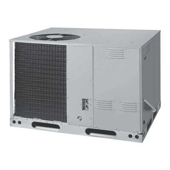
Installer's Guide
Ultra-Low NOx Series
Single Packaged Gas Heating/Electric Cooling
14 SEER/81% AFUE, 2 - 5 Ton Units
Models:
4YCL4024A1055A
4YCL4030A1070A
4YCL4036A1070A
4YCL4042A1100A
4YCL4048A1100A
4YCL4060A1100A
Only qualified personnel should install and service the equipment. The installation, starting up, and servicing of heating, ventilating, and air-conditioning
equipment can be hazardous and requires specific knowledge and training. Improperly installed, adjusted or altered equipment by an unqualified person
could result in death or serious injury. When working on the equipment, observe all precautions in the literature and on the tags, stickers, and labels that
are attached to the equipment.
August 2022
N N o o t t e e : : "Graphics in this document are for representation only. Actual model
may differ in appearance."
S S A A F F E E T T Y Y W W A A R R N N I I N N G G
18-EB42D1-1A-EN
Advertisement
Table of Contents

Related Manuals for Trane Ultra-Low NOx Series


Summary of Contents for Trane Ultra-Low NOx Series
- Page 1 Installer’s Guide Ultra-Low NOx Series Single Packaged Gas Heating/Electric Cooling 14 SEER/81% AFUE, 2 - 5 Ton Units Models: 4YCL4024A1055A 4YCL4030A1070A 4YCL4036A1070A 4YCL4042A1100A 4YCL4048A1100A 4YCL4060A1100A N N o o t t e e : : “Graphics in this document are for representation only. Actual model may differ in appearance.”...
- Page 2 This product complies with SJVAPCD 4905 and SCAQMD 1111 with NOx levels below 14ng/J when operated on natural gas. WARNING AVERTISSEMENT FIRE OR EXPLOSION HAZARD RISQUE D’INCENDIE OU D’EXPLOSION Failure to follow safety warnings exactly could Si les consignes de sécurité ne sont pas suivies à la lettre, cela peut entraîner la mort, de graves blessures ou des result in serious injury, death, or property dommages matériels.
-
Page 3: Table Of Contents
TABLE OF CONTENTS IMPORTANT SAFETY INFORMATION ......3 Verifying & Adjusting Firing Rate ........15 Manifold Pressure Adjustment ........15 REQUIREMENTS & CODES ........... 4 Verifying Over-Temperature Limit Control Operation ..15 Verifying Burner Operation ..........15 GENERAL INFORMATION ..........5 Verify Operation of the Supply Air Limit Switch ..... -
Page 4: Important Safety Information
IMPORTANT SAFETY INFORMATION WARNING: Please read all instructions before servicing this equipment. Pay attention to all safety warnings and any other special These units are fully charged with R-410A refrigerant notes highlighted in the manual. Safety markings are used and ready for installation. When a system is installed frequently throughout this manual to designate a degree or according to these instructions, no refrigerant level of seriousness and should not be ignored. -
Page 5: Requirements & Codes
• Before beginning the installation, verify that the unit model 90B), these instructions, and all applicable local codes. is correct for the job. The unit model number is printed on • Consult Table 6 (page 21), Table 7 (page 22), and the the data label. -
Page 6: General Information
GENERAL INFORMATION • Overhead obstructions, poorly ventilated areas, and areas subject to accumulation of debris should be avoided. Do not This single package gas heating / electric cooling unit is place the unit in a confined space or recessed area where designed only for outdoor rooftop or ground level slab discharge air from the unit to re-circulate into the condenser installations and can be readily connected to the high static duct... -
Page 7: Combustion Air & Venting Requirements
COMBUSTION AIR & VENTING REQUIREMENTS WARNING: AVERTISSEMENT: CARBON MONOXIDE POISONING HAZARD RISQUE D’INTOXICATION AU MONOXYDE DE CARBONE Failure to follow the steps outlined below for each appliance connected to the venting system Si les étapes décrites ci-dessous ne sont pas suivies pour chacun des appareils raccordés au système de being placed into operation could result in carbon ventilation au moment de sa mise en marche, cela peut... -
Page 8: General Information
General Information Figure 2 shows the proper installation of the vent cover assembly over the vent outlet on the exterior of the corner WARNING: panel. The fasteners used to secure the vent cover assembly have been included in the owner’s package. The following Installation methods other than those described in list summarizes the requirements for the location of the vent the following sections must comply with the National... -
Page 9: Circulating Air Supply
CIRCULATING AIR SUPPLY writing to: National Fire Protection Association, Batterymarch Park, Quincy, ME 02269 or visit www.NFPA.org on the web. WARNING: • Design the duct work according to Manual D by the Air Conditioning Contractors of America (ACCA). Products of combustion must not be allowed to •... -
Page 10: Unconditioned Spaces
• A suitable air filter must be installed upstream of the return air ducts as long as the following requirements are met: evaporator coil of the return air system. Refer to Table 1 • If using bottom discharge with return air ducts a roof curb for recommended external filter sizes. -
Page 11: Electrical Wiring
ELECTRICAL WIRING Install a 2 inch condensate trap in the drain line of the same size and prime with water. When connecting rigid drain line, hold the female fitting with a wrench to prevent twisting. Do WARNING: not over tighten! Refer to local codes and restrictions for proper condensate disposal requirements. -
Page 12: Pre-Electrical Checklist
Pre-Electrical Checklist • A wiring diagram is located on the inside cover of the control √ Verify the voltage, frequency, and phase of the supply source access panel of the outdoor unit. The installer should become match the specifications on the unit rating plate. familiar with the wiring diagram before making any electrical √... -
Page 13: Blower Speed
Blower Speed GAS SUPPLY & PIPING The blower speed is preset at the factory for fan only, heating, WARNING: and cooling operation. These factory settings are listed in Table 5 (page 20) Table 6 (page 21). For optimum system performance and comfort, it may be necessary to FIRE OR EXPLOSION HAZARD change the factory set speed. -
Page 14: Leak Check
Shut-Off Valve with 1 /8 NPT plugged tap NOTE: Some utilities require Shut-Off Valve to be 4 to 5 feet above floor Dripleg Automatic Gas Valve (with manual shut-off) Ground Joint Union Figure 7. Typical Gas Hookup - Right Side Entry •... -
Page 15: Start Up & Adjustments
√ Verify that the thermostat is wired correctly. The thermostat WARNING: function switch should be set to OFF and the thermostat fan switch should be set to AUTO. The reduction of input rating necessary for high Start-Up Procedure altitude installation may only be accomplished with factory supplied orifices. -
Page 16: Verifying & Adjusting Firing Rate
Table 5 (page 20) Table 6 (page 21). If the measured NOTE: Turning the screw clockwise increases the pressure temperature rise falls outside the specified range, it may be and turning the screw counter-clockwise decreases the necessary to change the blower speed. Lowering the blower pressure. -
Page 17: Operating Sequence
OPERATING SEQUENCE EQUIPMENT MAINTENANCE The operating sequences for the heating, cooling, and fan modes are described below. Refer to the field and unit wiring WARNING: diagram. See Figure 12 (page 24). Heating Cycle ELECTRICAL SHOCK, FIRE OR 1. The thermostat calls for heat by energizing the W terminal EXPLOSION HAZARD with 24VAC. - Page 18 3. Remove the louvered door from the unit. CAUTION: 4. Turn the gas control switch to the OFF position. 5. Remove the 2 screws securing the combustion air orifice The unit should never be operated without a filter plate to the air/fuel mixing tube (if needed to access the in the return air system.
-
Page 19: Troubleshooting
TROUBLESHOOTING DIAGNOSTIC DESCRIPTION GREEN LED RED LED If the unit does not operate in the cooling mode, check the Control Fault (No Power) following: • Is the thermostat operating properly? L1/Neutral Polarity Fault Flash Flash • Is the blower compartment doors in place? 1 Hour Lockout Alternating Flash •... -
Page 20: Figures & Tables
FIGURES & TABLES 3/4" NPT Female 24 9/10 Drain Connector DOWNFLOW SUPPLY DUCT OPENING Top View 47 1/2 13 1/2 13 1/2 13 3/10 DOWNFLOW 23 1/2 1.75 RETURN DUCT Horizontal Horizontal OPENING Supply Duct Return Duct Condensing Opening Opening Coil 16.0 16.0... -
Page 21: Airflow Data
Airflow Data EXTERNAL STATIC PRESSURE DROP - INCHES WATER COLUMN HEATING MODEL RISE MOTOR NUMBER RANGE (°F) (°F) (°F) (°F) (°F) (°F) (°F) (°F) (BTU/H) (ACFM) (ACFM) (ACFM) (ACFM) (ACFM) (ACFM) (ACFM) (ACFM) RISE RISE RISE RISE RISE RISE RISE RISE Tap T1** Tap T2... - Page 22 EXTERNAL STATIC PRESSURE DROP - INCHES WATER COLUMN MODEL MOTOR NUMBER SCFM SCFM SCFM SCFM SCFM SCFM SCFM SCFM Tap T1 Tap T2* Tap T3 1112 1050 4YCL4024A1055A Tap T4 1239 1170 1110 1049 Tap T5 1472 1411 1350 1295 1228 1164 1097...
-
Page 23: Gas Information
Gas Information CAPACITY OF BLACK IRON GAS PIPE (CU. FT. PER HOUR) FOR NATURAL GAS (SPECIFIC GRAVITY - 0.60) LENGTH OF PIPE RUN (FEET) NOMINAL PIPE DIAMETER (IN.) 1 1/4 1,050 1 1/2 1,600 1,100 Input To Furnace (Btu/hr) Cubic Feet Per Hour Required = Heating Value of Gas (Btu/Cu. - Page 24 POUR VOTRE SÉCURITÉ. FOR YOUR SAFETY READ À LIRE AVANT L’EMPLOI BEFORE OPERATING ATTENTION! L’inobservation de ces instructions WARNING: If you do not follow these instructions peut entraîner un incendie ou une explosion pouvant exactly, a fi re or explosion may result causing property causer des dam mages à...
-
Page 25: Wiring Diagram & Electrical Data
Wiring Diagram & Electrical Data HIGH XFMR R C Y G W Figure 12. Wiring Diagram for 230V / 60 Hz Unit with ECM Motor... -
Page 26: Refrigerant Charging
HEATING NOMINAL BLOWER INDUCER MINIMUM MAXIMUM VOLTAGE RANGE COMPRESSOR MODEL INPUT ELECTRICAL MOTOR MOTOR CIRCUIT OVER-CURRENT NUMBER AMPS (BTUH) MIN. MAX. SUPPLY AMPS AMPS AMPACITY PROTECTION 4YCL4024A1055A 55,000 230-60-1 12.8 58.3 20.8 4YCL4030A1070A 70,000 230-60-1 15.7 1.46 26.5 4YCL4036A1070A 70,000 230-60-1 18.6 1.46... -
Page 27: Refrigerant Charging Tables (Cooling Mode Only)
Refrigerant Charging Tables (Cooling Mode Only) Shaded boxes indicate flooded conditions. Rated design values. The suction pressure will be lower than design value if indoor air flow, entering dry bulb, or entering wet bulb temperatures are lower than design. 1. All pressures are listed in psig and all temperatures in ° F 2. - Page 28 Shaded boxes indicate flooded conditions. Rated design values. The suction pressure will be lower than design value if indoor air flow, entering dry bulb, or entering wet bulb temperatures are lower than design. 1. All pressures are listed in psig and all temperatures in ° F 2.
- Page 29 Shaded boxes indicate flooded conditions. Rated design values. The suction pressure will be lower than design value if indoor air flow, entering dry bulb, or entering wet bulb temperatures are lower than design. 1. All pressures are listed in psig and all temperatures in ° F 2.
-
Page 30: Furnace Components
FURNACE COMPONENTS The descriptions below are various functional components that affect the operation and shutting down of this furnace. Some of these components and their locations are shown in Figure 14. If any component of the furnace must be replaced, use only factory authorized replacement parts specified in the Replacement Parts List. -
Page 31: Installation Checklist
INSTALLATION CHECKLIST GAS SYSTEM INSTALLATION ADDRESS: Natural Gas Type: (circle one) Propane CITY: STATE: Gas pipe connections leak-tested? UNIT MODEL # Gas Line Pressure (in - W.C.): Is there adequate fresh air supply UNIT SERIAL # for combustion and ventilation? Unit Installed Minimum clearances Installation Altitude (FT.): Figure 1 (page... - Page 32 About Trane and American Standard Heating and Air Conditioning Trane and American Standard create comfortable, energy efficient indoor environments for residential applications. For more information, please visit www.trane.com or www.americanstandardair.com. The manufacturer has a policy of continuous data improvement and it reserves the right to change design and specifications without notice. We are committed to using environmentally conscious print practices.
Need help?
Do you have a question about the Ultra-Low NOx Series and is the answer not in the manual?
Questions and answers