Trane 4TTR3 Installation And Operation Manual
Hide thumbs
Also See for 4TTR3:
- Installer's manual (9 pages) ,
- Use and care manual (8 pages) ,
- Installation and operation manual (38 pages)
Table of Contents
Advertisement
ALL phases of this installation must comply with NATIONAL, STATE AND LOCAL CODES
IMPORTANT - This Document is customer property and is to remain with this unit. Please return to service informa-
tion pack upon completion of work.
These instructions do not cover all variations in systems or provide for every possible contingency to be met in connection with
the installation. Should further information be desired or should particular problems arise which are not covered sufficiently for the
purchaser's purposes, the matter should be referred to your installing dealer or local distributor.
Note: The manufacturer recommends installing only approved matched indoor and outdoor systems. Some of the benefits of
installing approved matched indoor and outdoor split systems are maximum efficiency, optimum performance and the best overall
system reliability.
Table of Contents
Section 1. Safety ..................................................................................... 2
Section 2. Unit Location Considerations ............................................. 3
Section 3. Unit Preparation .................................................................... 4
Section 4. Setting the Unit ..................................................................... 4
Section 5. Refrigerant Line Considerations ......................................... 4
Section 6. Refrigerant Line Routing ..................................................... 5
Section 7. Refrigerant Line Brazing ...................................................... 7
Section 8. Refrigerant Line Leak Check ............................................... 7
Section 9. Evacuation ............................................................................ 8
Section 10. Service Valves .................................................................... 8
Section 11. Electrical - Low Voltage ..................................................... 9
Section 12. Electrical - High Voltage .................................................. 10
Section 13. Start Up .............................................................................. 11
Section 14. System Charge Adjustment ............................................. 11
Section 15. Checkout Procedures ...................................................... 16
Section 16. Refrigerant Circuits (Reference only) ............................. 16
Section 17. Wiring Diagrams ............................................................... 17
Section 18. Pressure Curves ............................................................... 21
Installation and Operation Manual
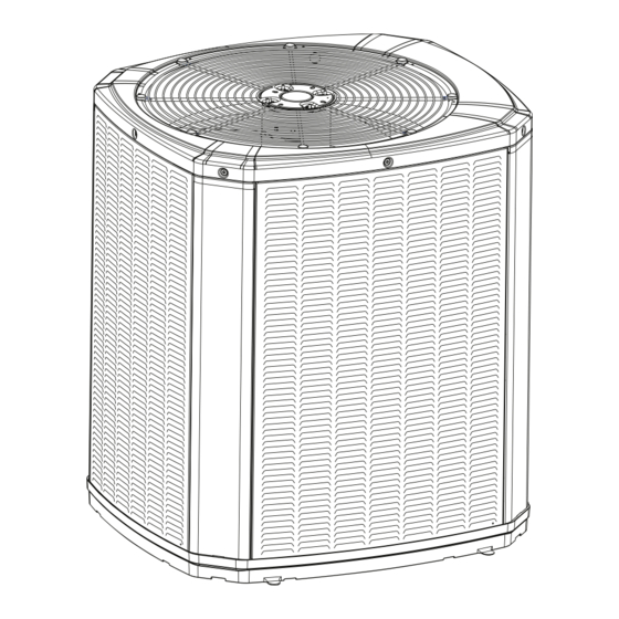
Condensing Units
4TTR3
18-AC79D1-10E-EN
Advertisement
Table of Contents

Subscribe to Our Youtube Channel
Related Manuals for Trane 4TTR3


Summary of Contents for Trane 4TTR3
-
Page 1: Table Of Contents
18-AC79D1-10E-EN Installation and Operation Manual Condensing Units 4TTR3 ALL phases of this installation must comply with NATIONAL, STATE AND LOCAL CODES IMPORTANT – This Document is customer property and is to remain with this unit. Please return to service informa- tion pack upon completion of work. -
Page 2: Section 1. Safety
Section 1. Safety WARNING WARNING LIVE ELECTRICAL COMPONENTS! This information is intended for use by individuals During installation, testing, servicing, and trouble- possessing adequate backgrounds of electrical and shooting of this product, it may be necessary to work mechanical experience. Any attempt to repair a central with live electrical components. -
Page 3: Section 2. Unit Location Considerations
Section 2. Unit Location Considerations 2.1 Unit Dimensions and Weight Table 2.1 Unit Dimensions and Weight Models H x D x W (in) Weight* (lb) 4TTR3018N 29 x 26 x 29 4TTR3024N 29 x 26 x 29 4TTR3030N 29 x 30 x 33 4TTR3036N 29 x 30 x 33 4TTR3042N... -
Page 4: Section 3. Unit Preparation
2.4 Cold Climate Considerations NOTE: It is recommended that these precautions be taken for units being installed in areas where snow accumula- tion and prolonged below freezing temperatures occur. • Units should be elevated 3-12 inches above the pad or roof top, depending on local weather. This additional height will allow drainage of snow and ice melted during defrost cycle prior to its refreezing. -
Page 5: Section 6. Refrigerant Line Routing
5.2 Factory Charge The outdoor condensing units are factory charged with the system charge required for the outdoor condensing unit, ten (10) feet of tested connecting line, and the smallest rated indoor evaporative coil match. Always verify proper system charge via subcooling (TXV/EEV) or superheat (fixed orifice) per the unit nameplate. 5.3 Required Refrigerant Line Length Determine required line length and lift. - Page 6 8 Feet Maximum Joist/Rafter Isolator Side View 8 Feet Maximum Line Set Secure Vapor line from joists using isolators every 8 ft. Secure Liquid Line directly to Vapor line using tape, wire, or other appro- priate method every 8 ft. Isolation From Joist/Rafter 8 Feet Maximum Wall...
-
Page 7: Section 7. Refrigerant Line Brazing
Section 7. Refrigerant Line Brazing 7.1 Braze The Refrigerant Lines STEP 1 - Remove caps or plugs. Use a deburing tool to debur the pipe ends. Clean both internal and external surfaces of the tubing using an emery cloth. STEP 2 - Remove the pressure tap cap and valve cores from both service valves. STEP 3 - Purge the refrigerant lines and indoor coil with dry nitrogen. -
Page 8: Section 9. Evacuation
Section 9. Evacuation 9.1 Evacuate the Refrigerant Lines and Indoor Coil Important: Do not open the service valves until the refrigerant lines and indoor coil leak check and evacuation are complete. STEP 1 - Evacuate until the micron gauge reads no higher than 350 microns, then close off the valve to the vacuum pump. -
Page 9: Section 11. Electrical - Low Voltage
Section 11. Electrical - Low Voltage 11.1 Low Voltage Maximum Wire Length Table 11.1 defines the maximum total length of Table 11.1 low voltage wiring from the outdoor unit, to the 24 VOLTS indoor unit, and to the thermostat. WIRE SIZE MAX. -
Page 10: Section 12. Electrical - High Voltage
With Furnace With Variable Speed Furnace Outdoor Outdoor Thermostat Furnace Thermostat Furnace Unit Unit 24 VAC HOT 24 VAC HOT 24 VAC 24 VAC Common Common COOL COOL HEATING HEATING • Units with pigtails require wirenuts for connections. Cap all unused wires. •... -
Page 11: Section 13. Start Up
Section 13. Start Up 13.1 System Start Up STEP 1 - Ensure Sections 7 through 12 have been completed. STEP 2 - Set System Thermostat to OFF. STEP 3 - Turn on disconnect(s) to apply power to the indoor and outdoor units. STEP 4 - Wait one (1) hour before starting the unit if compressor crankcase heater accessory is used and the Outdoor Ambient is below 70ºF. - Page 12 14.2 Subcooling Charging in Cooling (Above 55º F Outdoor Temp.) STEP 1 - Use the refrigerant line total length and lift measurements from Section 5.3. Total Line Length = __________ Ft. LIFT Vertical Change (Lift) = __________ Ft. STEP 2 - Determine the final subcooling value using total Line Length and Lift measured in STEP 1 and the charts below. 018N Models 024N Models SUBCOOL CHARGING CHART CORRECTIONS TABLE (FOR LINE LENGTH AND RISE)
- Page 13 STEP 3 - Stabilize the system by operating for a minimum of 20 minutes. At startup, or whenever charge is removed or added, the system must be operated for a minimum of 20 minutes to stabilize before accurate measurements can be made. STEP 4 - Measure the liquid line temperature and pressure at the outdoor unit’s service valve.
- Page 14 PRESSURE CURVE SAMPLE Cooling @ 1450 SCFM Heating @ 1350 SCFM INDOOR ENTERING INDOOR ENTERING WET BULB CURVES DRY BULB CURVES TOP TO BOTTOM TOP TO BOTTOM 80, 70, AND 60 DEG F. 71, 67, 63 AND 59 DEG F. OUTDOOR TEMPERATURE (Degree F) INDOOR ENTERING INDOOR ENTERING...
- Page 15 14.3 Subcooling Charging Below 55º F Outdoor Temp. (In Heating Only) The Subcooling Charging method in cooling is not recommended below 55º F outdoor temperature. The recommended method of charging at outdoor temperatures below 55º F is weighing in the charge. Return when weather conditions permit charge verification through subcooling.
-
Page 16: Section 15. Checkout Procedures
Section 15. Checkout Procedures 15.1 Operational And Checkout Procedures Final phases of this installation are the unit Operational and Checkout Procedures. To obtain proper performance, all units must be operated and charge adjustments made. Important: Perform a final unit inspection to be sure that factory tubing has not shifted during shipment. Adjust tubing if nec- essary so tubes do not rub against each other when the unit runs. -
Page 17: Section 17. Wiring Diagrams
Section 17. Wiring Diagrams 18-AC79D1-10E-EN... - Page 18 18-AC79D1-10E-EN...
- Page 19 18-AC79D1-10E-EN...
- Page 20 18-AC79D1-10E-EN...
-
Page 21: Section 18. Pressure Curves
Section 18. Pressure Curves COOLING PERFORMANCE CAN BE CHECKED WHEN THE OUTDOOR TEMP IS ABOVE 65 DEG F. TO CHECK COOLING PERFORMANCE, SELECT THE PROPER INDOOR CFM, ALLOW PRESSURES TO STABILIZE. MEASURE INDOOR WET BULB TEMPERATURE, OUTDOOR TEMPERATURE, LIQUID AND SUCTION PRESSURES. ON THE PLOTS LOCATE OUTDOOR TEMPERATURE (1); LOCATE INDOOR WET BULB (2);... - Page 22 The AHRI Certified mark indicates Trane U.S. Inc. participation in the AHRI Certification program. For verification of individual certified products, go to ahridirectory.org. Trane has a policy of continuous data improvement and it reserves the right to change design and specifications without notice. We are committed to using environmentally conscious print practices.
Need help?
Do you have a question about the 4TTR3 and is the answer not in the manual?
Questions and answers