Table of Contents
Advertisement
Quick Links
Advertisement
Table of Contents

Related Manuals for iglu Inuit 6I


Summary of Contents for iglu Inuit 6I
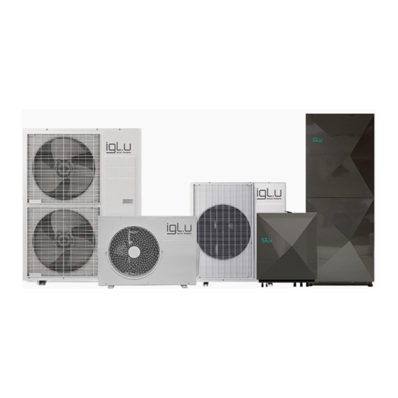
- Page 1 INSTALLATION MANUAL AIR-TO-WATER HEAT PUMP IGLU® INUIT...
-
Page 2: Table Of Contents
TABLE OF CONTENT INTRODUCTION ............................................5 PURPOSE..............................................5 LIABILITY ..............................................5 WARRANTY ..............................................5 PRODUCT PACKAGING AND TRANSPORTATION ................................5 SAFETY PRECAUTION ........................................... 6 WARNING ..............................................6 PRODUCT SPECIFICATION ........................................8 PRODUCT LINE-UP ..........................................8 ACCESSORIES ............................................10 UNIT SPECIFICATION (without water tank) ..................................11 UNIT SPECIFICATION (with water tank) .................................... - Page 3 OUTLET AND INLET SCHEME OF INDOOR UNIT................................. 39 ELECTRICAL SCHEMES .......................................... 41 CONNECTING THE CABLES ....................................... 44 SPECIFICATION OF CONNECTION CABLES (COMMON IN USE) ..........................44 INSTALLING THE EARTH WIRE ......................................47 EARTHING THE POWER CABLE ......................................47 HOW TO CONNECT YOUR EXTENDED POWER CABLES .............................. 48 REFRIGERANT PIPING WORK........................................
- Page 4 Correct Disposal of This Product (Waste Electrical & Electronic Equipment) (Applicable in countries with separate collection systems) This marking on the product, accessories or literature indicates that the product and its electronic accessories (e.g., charger, headset, USB cable) should not be disposed of with other household waste at the end of their working life.
-
Page 5: Introduction
INTRODUCTION This installation manual provides information on the installation of the IGLU heat pump. It is an integral part of the product and must be easily accessible to the installer. The manual must be available throughout the life of the device. In the event of a change in the owners of the device, the manual must be passed on to the new owners or users. -
Page 6: Safety Precaution
To prevent electric shocks, fires, or injuries, always stop the unit, and disable the protection switch and • contact. IGLU TECH’s technical support if the unit produces smoke if the power cable is hot or damaged or if the unit • is very noisy. - Page 7 When extension wiring is required due to power line damage, refer to "How to connect your extended power • cables" in the installation manual. Do not use means to accelerate the defrost operation or to clean, other than those recommended by Iglu • Tech.
-
Page 8: Product Specification
PRODUCT SPECIFICATION PRODUCT LINE-UP MODEL NAME MODEL REMARKS IGLU® Inuit 6I Without water tank IGLU® Inuit 6WTI With water tank IGLU® Inuit 9I Without water tank IGLU® Inuit 9WTI With water tank IGLU® Inuit 12I Without water tank... - Page 9 MODEL NAME MODEL REMARKS IGLU® Inuit 12WTI With water tank IGLU® Inuit 16I Without water tank IGLU® Inuit 16WTI With water tank...
-
Page 10: Accessories
• The base heater inside the outdoor unit works in accordance with the weather outdoors. • IGLU® Inuit 6I/ IGLU® Inuit 6WTI IGLU® Inuit 9I/ IGLU® Inuit 9WTI IGLU® Inuit 12I/ IGLU® Inuit 12WTI IGLU® Inuit 16I/ IGLU® Inuit 16WTI... -
Page 11: Unit Specification (Without Water Tank)
UNIT SPECIFICATION (without water tank) Units 6 kW 9 kW 12 kW 16 kW Air-water used Nominal Heating capacity/ COP (A7/W35) kW/ W/W 6,0/ 4,92 9,0/ 4,81 12,0/ 4,63 16,0/ 4,26 Nominal Heating capacity/ COP (A2/W35) kW/ W/W 5,2/ 3,51 7,7/ 3,41 12,79/ 3,49 15,93/3,26... -
Page 12: Unit Specification (With Water Tank)
UNIT SPECIFICATION (with water tank) Units 6 kW 9 kW 12 kW 16 kW Air-water used Nominal Heating capacity/ COP (A7/W35) kW/ W/W 6,0/ 4,92 9,0/ 4,81 12,0/ 4,63 16,0/ 4,26 Nominal Heating capacity/ COP (A2/W35) kW/ W/W 5,2/ 3,51 7,7/ 3,41 12,79/ 3,49 15,93/3,26... -
Page 13: Capacity Table
CAPACITY TABLE IGLU® Inuit 6I / IGLU® Inuit 6WTI LWT(℃) HC(kW) PI(kW) HC(kW) PI(kW) HC(kW) PI(kW) HC(kW) PI(kW) HC(kW) PI(kW) HC(kW) PI(kW) HC(kW) PI(kW) Tamb(℃ 4,69 1,63 4,56 1,75 4,35 1,97 4,18 2,10 4,01 2,32 5,40 1,74 5,25 1,87 5,00... - Page 14 IGLU® Inuit 16I / IGLU® Inuit 16WTI LWT(℃) Tamb(℃ HC(kW) PI(kW) HC(kW) PI(kW) HC(kW) PI(kW) HC(kW) PI(kW) HC(kW) PI(kW) HC(kW) PI(kW) HC(kW) PI(kW) 10,75 5,45 10,45 5,83 9,88 6,18 9,45 6,12 12,47 5,13 12,12 5,49 11,65 5,94 11,20 6,10 10,75...
-
Page 15: Main Components
MAIN COMPONENTS DIMENSIONS IGLU® Inuit 6I (outdoor unit) IGLU® Inuit 6I (indoor unit) IGLU® Inuit 6WTI (outdoor unit) IGLU® Inuit 6I (outdoor unit) IGLU® Inuit 6I (outdoor unit) - Page 16 IGLU® Inuit 6WTI (indoor unit)
- Page 17 IGLU® Inuit 9I (outdoor unit) IGLU® Inuit 9I (indoor unit)
- Page 18 IGLU® Inuit 9WTI (outdoor unit) IGLU® Inuit 9WTI (indoor unit)
- Page 19 IGLU® Inuit 12I / IGLU® Inuit 16I (outdoor unit) IGLU® Inuit 12I / IGLU® Inuit (indoor unit)
- Page 20 IGLU® Inuit 12WTI / IGLU® Inuit 16WTI (outdoor unit) IGLU® Inuit 12WTI / IGLU® Inuit 16WTI (indoor unit)
-
Page 21: Instaling The Unit
If the product is installed within 500m of the seashore, special anti-corrosion treatment is required. ❋ Please contact your local IGLU TECH representative for further details. The protection wall should be constructed with a solid material that can block the sea breeze and the height •... -
Page 22: Heating System Filling
Depending on the condition of the power supply, unstable power or voltage may cause malfunction of the parts or control system. (At the ship or places using power supply from the electric generator, etc.). HEATING SYSTEM FILLING Set the pressure of the heating circuit in the expansion vessel to 1.5 bar. Usually, the replenishment of the heating circuit is stationary and pre-connected to the water inlet, in which case the replenishment takes place individually according to the system. -
Page 23: Caution
CAUTION Do not install the Air to Water Heat Pump in the following places. The place where there is mineral oil or arsenic acid. There is a chance that parts may get damaged due to burned resin. • The capacity of the heat exchanger may be reduced or the Air to Water Heat pump may be out of order. The place where corrosive gas such as sulfurous acid gas generates from the vent pipe or air outlet. -
Page 24: Preparation Of Fire Extinguisher
Safe parts are the ones with which the worker can work in a flammable atmosphere. Other parts may result in • ignition due to leakage. Replace components only with parts specified by Iglu tech. Other parts may result in the ignition of refrigerant in • the atmosphere from a leak. -
Page 25: Leakage Detection Methods
LEAKAGE DETECTION METHODS The leakage detector shall be calibrated in a refrigerant-free area. Make sure that the detector is not a potential source of ignition. The leakage detector shall be set to the LFL (lower flammability limit). ... -
Page 26: Moving The Outdoor Unit By Wire Rope
There must be no aggressive chemicals in the environment. Indoor units should not be installed close to walls; the front of the unit should always be accessible. A drainage system must be provided in the room where the unit is installed. In this case, leaking water can be drained. -
Page 27: Space Requirements For Outdoor Unit
SPACE REQUIREMENTS FOR OUTDOOR UNIT WHEN INSTALLING ONE OUTDOOR UNIT... -
Page 28: When Installing More Than One Outdoor Unit
WHEN INSTALLING MORE THAN ONE OUTDOOR UNIT The units must be installed according to distances declared, to permit accessibility from each side, either to guarantee the correct operation of maintenance or repair products. The unit’s parts must be reachable and removable completely under safety conditions (for people or things). -
Page 29: Space Requirements For Indoor Unit
SPACE REQUIREMENTS FOR INDOOR UNIT WHEN INSTALLING ONE INDOOR UNIT WITH WATER TANK IGLU® Inuit 6WTI IGLU® Inuit 9WTI IGLU® Inuit 12WTI IGLU® Inuit 16WTI... -
Page 30: When Installing More Than One Indoor Unit
WHEN INSTALLING MORE THAN ONE INDOOR UNIT WITH WATER TANK IGLU® Inuit 6WTI IGLU® Inuit 9WTI IGLU® Inuit 12WTI IGLU® Inuit 16WTI... -
Page 31: When Installing One Indoor Unit
WHEN INSTALLING ONE INDOOR UNIT WITHOUT WATER TANK IGLU® Inuit 6I IGLU® Inuit 9I IGLU® Inuit 12I IGLU® Inuit 16I... -
Page 32: When Installing One Indoor Unit
WHEN INSTALLING ONE INDOOR UNIT WITHOUT WATER TANK IGLU® Inuit 6I IGLU® Inuit 9I IGLU® Inuit 12I IGLU® Inuit 16I... -
Page 33: Outdoor Unit Installation
Fix the outdoor unit with anchor bolts The anchor bolt must be 20 mm or higher from the base surface. GLU® Inuit 6I/ IGLU® Inuit 6WTI GLU® Inuit 9I/ IGLU® Inuit 9WTI GLU® Inuit 12I/ IGLU® Inuit 12WTI GLU® Inuit 16I/ IGLU® Inuit 16WTI ... -
Page 34: Outdoor Unit Support
OUTDOOR UNIT SUPPORT Outdoor unit installed on the wall by rack: Ensure the wall will be able to suspend the weight of the rack and outdoor unit. Install the rack as close to the column as possible. Install proper grommet to reduce noise and residual vibration. -
Page 35: Drain Work
If drain work is not enough, it can lead to system performance degradation and system damage. GLU® Inuit 6I/ IGLU® Inuit 6WTI GLU® Inuit 9I/ IGLU® Inuit 9WTI GLU® Inuit 12I/ IGLU® Inuit 12WTI GLU® Inuit 16I/ IGLU® Inuit 16WTI... - Page 36 1. Prepare a water drainage channel around the foundation, to drain wastewater from around the unit. 2. If the water drainage of the unit is not easy, please build up the unit on a foundation of concrete blocks, etc. (the height of the foundation should be a maximum of 150 mm).
-
Page 37: Heavy Snowfall Area
HEAVY SNOWFALL AREA When using the air conditioner in the heating mode, ice may accumulate. During de-icing (defrost operation), the condensed water must be drained off safely. For the air conditioner to operate well, you must follow the instructions below. Make space more than 80mm between the bottom of the outdoor unit and the ground for installation. -
Page 38: Selecting A Location In Cold Climates
SELECTING A LOCATION IN COLD CLIMATES When operating the unit in a low outdoor ambient temperature, be sure to follow the instructions described below. To prevent exposure to wind, install the unit with its suction side facing the wall. ... -
Page 39: Outlet And Inlet Scheme Of Indoor Unit
OUTLET AND INLET SCHEME OF INDOOR UNIT IGLU® Inuit 6WTI IGLU® Inuit 9WTI IGLU® Inuit 12WTI IGLU® Inuit 16WTI A – Refrigerant line (outlet) B – Refrigerant line (inlet) C – Cold water in (outlet) D – Hot water out (inlet) E –... - Page 40 IGLU® Inuit 6I IGLU® Inuit 9I IGLU® Inuit 12I IGLU® Inuit 16I A – Refrigerant line (outlet) B – Refrigerant line (inlet) C – Heating return (outlet)) D – Heating supply (inlet) E – Heating supply for an external water tank (outlet)
-
Page 41: Electrical Schemes
ELECTRICAL SCHEMES GLU® Inuit 6I/ IGLU® Inuit 6WTI GLU® Inuit 9I/ IGLU® Inuit 9WTI GLU® Inuit 12I/ IGLU® Inuit 12WTI GLU® Inuit 16I/ IGLU® Inuit 16WTI • Make sure to install the circuit breaker with the over-current and electric leakage protection. - Page 42 IGLU® Inuit 9WTI Contact sets IGLU® Inuit 6WTI IGLU® Inuit 12WTI IGLU® Inuit 16WTI 1 Feeding thermoficate T 2 COM 3 Return thermoficate T 4 COM 5 Boiler T 6 COM 7 Liquid Agent T 8 COM 9 Indoor temperature sensor NTC10K...
-
Page 44: Connecting The Cables
CONNECTING THE CABLES GLU® Inuit 6I/ IGLU® Inuit 6WTI RATED VOLTAGE RANGE Volt Min. Circuit Max. Circuit amps. amps. 220-240 16.0A 20.0A GLU® Inuit 9I/ IGLU® Inuit 9WTI RATED VOLTAGE RANGE Volt Min. Circuit Max. Circuit amps. amps. 380-415 10.0A 16.1A... - Page 45 GLU® Inuit 6I/ IGLU® Inuit 6WTI IGLU® Inuit 9I/ IGLU® Inuit 9WTI IGLU® Inuit 12I/ IGLU® Inuit 12WTI IGLU® Inuit 16I/ IGLU® Inuit 16WTI...
- Page 46 IGLU® Inuit 6I/ IGLU® Inuit 6WTI When removing the outer cover of the power cable, use the appropriate tools to prevent damaging the inner cover. Make sure to place the outer cover of the power cable and the communication cable, at least 20 mm into the electrical parts.
-
Page 47: Installing The Earth Wire
Connect the cables to the terminal board using the compressed ring terminal. Connect the rated cables only. Connect using a wrench that can apply the rated torque to the screws. If the terminal is loose, fire may occur caused by an arc. If the terminal is connected too firmly, the terminal may be damaged. -
Page 48: How To Connect Your Extended Power Cables
HOW TO CONNECT YOUR EXTENDED POWER CABLES Prepare your tools. Tools Specification Shape Crimping pliers MH-14 Connection sleeve (mm) 20x6.5 (HxOD) Insulation tape Width 19mm Contraction tube (mm) 70x8 (LxOD) As shown in the figure, peel off the shields from the rubber and wire of the power cable. Peel off 20 mm of cable shields from the pre-installed tube. - Page 49 Using a crimping tool, compress the two points and flip them over and compress another two points in the same location. The compression dimension should be 8.0. After compressing it, pull both sides of the wire to make sure it is firmly pressed. ...
-
Page 50: Refrigerant Piping Work
REFRIGERANT PIPING WORK Install the refrigerant pipe within the maximum allowable length, the difference in height and length after the first branch pipe. The pressure of the R-410A is high. Use only rated refrigerant pipe and follow the installation method. ... -
Page 51: Instaling Indoor Unit
TYPICAL APPLICATION EXAMPLES The application examples given below are for illustration purposes only. When the IGLU Air-to-Water Heat Pump system is used in series with another heat source (e.g., gas boiler), ensure that the return water temperature does not exceed 55 °C. -
Page 52: Main Components
MAIN COMPONENTS GLU® Inuit 6I GLU® Inuit 9I GLU® Inuit 12I GLU® Inuit 16I Name Backup heater element Plate heat exchanger Expansion tank Three-way valve Water pump Antenna Air relief mechanical valve... - Page 53 GLU® Inuit 6 WTI GLU® Inuit 9 WTI GLU® Inuit 12 WTI GLU® Inuit 16 WTI Name Water tank Three-way valve Backup heater element Water pump Flow sensor Antenna Air relief mechanical valve Wireless communication module Expansion tank Plate heat exchanger Drain valve...
-
Page 54: Selecting The Refrigerant Pipe
SELECTING THE REFRIGERANT PIPE Outdoor unit capacity (kW) Liquid side Gas side (mm) (mm) ø6.35 ø15.88 GLU® Inuit 6I/ GLU® Inuit 6WTI ø6.35 ø 15.88 GLU® Inuit 9I/ GLU® Inuit 9WTI ø 9.52 ø 15.88 GLU® Inuit 12I/ GLU® Inuit 12WTI ø... - Page 55 Put a flare nut slightly into the pipe and modify the flare. Outer diameter Depth [A (mm)] Flaring Size [B [D(mm)] (mm)] ø 6.35 8.7~9.1 ø 9.52 12.8~13.2 ø 12.70 16.2~16.6 ø 15.88 19.3~19.7 ø 19.05 23.6~24.0 Check that you flared the pipe correctly. The below figures show some examples of incorrectly flared pipes. ...
-
Page 56: Refrigerant Piping Work
REFRIGERANT PIPING WORK Tighten the nuts to the specified torques. If overtightened, the nuts could be broken so refrigerant may leak. Protect or enclose refrigerant tubing to avoid mechanical damage. Keep the piping length at a minimum to minimize the additional refrigerant charge due to piping extension. ... -
Page 57: Insulating The Refrigerant Pipe
INSULATING THE REFRIGERANT PIPE You must check if there is a gas leak before completing the installation process. Use EPDM insulation that meets the following conditions. ITEM UNIT STANDARD REMARKS Density g/cm² 0.048~0.096 KSM 3014-01 Dimension change route by -5 or less heat Water absorption rate... -
Page 58: Performing The Refrigerant Gas Leak Test
PERFORMING THE REFRIGERANT GAS LEAK TEST Use a manifold gauge for R-410A to prevent the inflow of foreign substances and resist internal pressure. Pressure test with dry oxygen-free nitrogen only. Apply pressure to the liquid side pipe and gas You may get injured when the joint on the high- side pipe with Nitrogen gas of 4.6 MPa (46.9 pressure side detaches and the gas encounters your... -
Page 59: Vacuum Drying
VACUUM DRYING Use the tools for R-410A only to prevent the inflow of foreign substances and resist against internal pressure. Use the vacuum pump with the check valve to prevent pump oil from flowing backward while the vacuum pump stopped suddenly. ... -
Page 60: Selecting An Additional Refrigerant Charge
50 g/m 50 g/m Additional Charge(g) = (L1-15)*20 (IGLU® Inuit 6I/ IGLU® Inuit 6WTI, IGLU® Inuit 9I/ IGLU® Inuit 9WTI) Additional Charge(g) = (L1-15)*50 (IGLU® Inuit 12I/ IGLU® Inuit 12WTI, IGLU® Inuit 16I/ IGLU® Inuit 16WTI) *L1-TOTAL LENGTH OF LIQUID PIPE EXAMPLES: IGLU®... - Page 61 CHARGING REFRIGERANT This product contains fluorinated greenhouse gases. Do not vent gases into the atmosphere. Inform the user if the system contains 5 tCO2e or more fluorinated greenhouse gases. In this case, it must be checked for leakage at least once every 12 months, according to regulation No. 517/2014. This activity must be covered by qualified personnel only.
-
Page 62: Adding Refrigerant
ADDING REFRIGERANT The R-410A refrigerant is blended. Add only liquid refrigerant. Measure the quantity of the refrigerant depending on the length of the liquid side pipe. Add a fixed quantity of the refrigerant using a scale. ❋ Adding refrigerants in cooling conditions ❋... -
Page 63: To Close The Valve Stem
TO CLOSE THE VALVE STEM 1. Open the cap and turn the valve stem clockwise by using a hexagonal wrench. Tightening torque (N•m) Outer Operating torque (N•m) Diameter (mm) Body cap Charging port Stem ø 6.35 Max 5 ø 9.52 Max 5 20 ~ 25 10 ~ 12... -
Page 64: Checking Correct Grounding
CHECKING CORRECT GROUNDING If the power distribution circuit does not have a grounding or the grounding does not comply with specifications, an A grounding electrode must be installed. The corresponding accessories are not supplied with the Air to Water Heat pump. -
Page 65: Setting The Option Switch And Function Of The Keys
(IGLU® Inuit 6I/ IGLU® Inuit 6WTI) • 3 phases power supply: R, S, T, N (IGLU® Inuit 9I/ IGLU® Inuit 9WTI, IGLU® Inuit 12I/ IGLU® Inuit 12WTI, IGLU® Inuit 16I/ IGLU® Inuit 16WTI) 2. Check that you have connected the power and communication cables correctly. (If the power cable and communication cables one mixed up or connected incorrectly, the PCB will be damaged.) -
Page 66: Setting The Option
4: Down limit 2: Defrosting 3: Over-load 4: Discharge 5: Total current IPM temp. 10s digit 1s digit °C long-1 Main Micom Year (Dec) Month (Hex) Day (two Day (One version digits) digit) long-1 Inverter Micom Year (Dec) Month (Hex) Day (two Day (One and 1... - Page 67 OPTION INPUT SEG1 SEG2 SEG3 SEG4 FUNCTION OF THE OPTION UNIT Channel Main Automatic address setting (default) Manual address address setting (0 to 15) Base heater Main Enabled (default) Disabled Operation mode Main Heat Pump (default) Heating Only Snow Main Disabled (default) Enabled accumulation prevention...
-
Page 68: Pump Down Procedure
PUMP DOWN PROCEDURE OBJECTIVE OF PUMPING DOWN For product repairs and indoor unit relocation, the pump-down operation must be done to recover the refrigerant into the outdoor unit. CAUTIONS WHEN PERFORMING PUMP DOWN The product limits the amount of refrigerant in the outdoor unit due to its slim design. ... -
Page 69: Collecting Refrigerant In Refrigerant Vessel Before Pump Down Operation
COLLECTING REFRIGERANT IN REFRIGERANT VESSEL BEFORE PUMP DOWN OPERATION If the amount of refrigerant in the system exceeded the maximum allowable limit, reduce the amount of refrigerant by following the below instructions before the pump down operation. 1. Prepare an exclusive rechargeable refrigerant vessel, scale, and manifold gauge. 2. -
Page 70: Completing The Installation
COMPLETING THE INSTALLATION Check the following after completing the installation. • Check the external surface and the inside of the outdoor unit. INSTALLATION OUTDOOR • Is there any possibility of a short circuit? UNIT • Is the place well-ventilated and ensures space for service? •... -
Page 71: Troubleshooting
TROUBLESHOOTING • Incorrect handling of the thermostat, safety valve, or other valves may lead to tank rupture. When servicing the unit follow the instructions carefully: • Always turn off the main power supply when the water supply is being shut off. •... - Page 72 [Inverter] DC LINK voltage sensor error Outdoor Unit Outdoor unit EEPROM Read/Write Error Outdoor Unit Outdoor unit EEPROM Read/Write Error (OTP error) Outdoor Unit IPM (IGBT Module) or PFCM temperature sensor Error Outdoor Unit Outdoor Unit Fan2 error Outdoor Unit PFC Overload Error Outdoor Unit Input current sensor error...
- Page 73 Notes _______________________________________________________________________ _______________________________________________________________________ _______________________________________________________________________ _______________________________________________________________________ _______________________________________________________________________ _______________________________________________________________________ _______________________________________________________________________ _______________________________________________________________________ _______________________________________________________________________ _______________________________________________________________________ _______________________________________________________________________ _______________________________________________________________________ _______________________________________________________________________ _______________________________________________________________________ _______________________________________________________________________ _______________________________________________________________________ _______________________________________________________________________ _______________________________________________________________________ _______________________________________________________________________ _______________________________________________________________________ _______________________________________________________________________ _______________________________________________________________________ _______________________________________________________________________ _______________________________________________________________________ _______________________________________________________________________ _______________________________________________________________________ _______________________________________________________________________ _______________________________________________________________________ INSTALLATION MANUAL 1.0 © UAB IGLU TECH 2023...
Need help?
Do you have a question about the Inuit 6I and is the answer not in the manual?
Questions and answers