Lütze DIOLINE PLC Operating Instructions Manual
Hide thumbs
Also See for DIOLINE PLC:
- Operating instructions manual (141 pages) ,
- Operating instructions manual (45 pages)
Table of Contents
Advertisement
Quick Links
Advertisement
Table of Contents

Related Manuals for Lütze DIOLINE PLC


Summary of Contents for Lütze DIOLINE PLC
- Page 1 Operating Instructions DIOLINE PLC MVB(EMD)-PBM, Part-No. 746050 Version 02...
- Page 2 Lütze Transportation GmbH Bruckwiesenstraße 17-19 D-71384 Weinstadt Tel.: +49 (0) 7151 6053-545 Fax: +49 (0) 7151 6053-6545 Sales.Transportation@luetze.de www.luetze-transportation.com...
-
Page 3: Table Of Contents
▪ DIOLINE PLC Table of Contents Table of Contents Introduction....................... 3 General information..................4 Symbol description ........................4 2.1.1 Handling notes..........................4 Copyright ............................. 4 Disclaim of liability ........................4 Related documents........................5 Application manual valid with these operating instructions............5 Safety ......................... - Page 4 ▪ DIOLINE PLC Table of Contents Maintenance ....................42 13.1 Maintenance software........................ 42 Demounting..................... 43 Shutdown and disposal ................. 44 Service ......................45 Revision of the document................46...
-
Page 5: Introduction
▪ DIOLINE PLC Introduction Introduction This manual is a component of the product: DIOLINE PLC. To avoid hazardous situations, these instructions must be read and understood before installing, operating, maintaining, or dismantling the device NOTICE This applies to every person who is getting in touch with the product. -
Page 6: General Information
▪ DIOLINE PLC General information General information Symbol description This document contains safety information, which is characterized by a signal word in combination with a specific colour to indicate the warning level. The information highlights possible dangers and gives instructions on how to avoid them. -
Page 7: Related Documents
The real-time capability of the controllerRelated Documents Related documents The programming environment of the DIOLINE PLC is a product of the company KW Software and Hilscher. The companies are responsible for the documentation and the compliance of standards. This document contains short parts of the software documentation. -
Page 8: Safety
▪ as a high capacity gateway for the realization of different vehicle specific bus signals Use the DIOLINE PLC just for the listed cases and just with external devices recommended and allowed by Lütze Transportation GmbH. Recipients This document addresses planners, project managers and programmers. It also addresses the operating personnel who are responsible for the initial operation, the operation and for the maintenance of the products and systems. -
Page 9: Responsibility Of The Operator
▪ DIOLINE PLC Safety Responsibility of the operator Since the device is used in a commercial area, the operator of the device is subject to legal obligations for occupational safety: ▪ The operator of the device is obliged to instruct the operating personnel and to inform himself about the industrial safety regulations. -
Page 10: Labeling
▪ DIOLINE PLC Safety Labeling Oberve the adhesive labels. ▪ Keep them readable. ▪ In case of a malfunction the part number and the serial number might be needed. The label contains the following information as an example: 1. Part number 2. -
Page 11: Reconstruction And Modifications Of The Product
▪ DIOLINE PLC Safety Reconstruction and modifications of the product Reconstructions and modifications of the product can cause property damages or personal injuries Do not reconstruct or modify the product if the manufacturer does not allow it explicit in writing. -
Page 12: Product Overview
The software can handle multiuser projects over a network access. There are several options regarding the interfaces and software. The DIOLINE PLC can be used to automate simple vehicles, as a subsystem controller or as a powerful gateway to implement various vehicle-specific bus signals. -
Page 13: Hardware Options
▪ DIOLINE PLC Product Overview Hardware options Option Item Number DIOLINE PLC-COM-COM-LUE 746026 DIOLINE PLC-COM-CAN-LUE 746027 DIOLINE PLC-MVB(EMD)-CAN-LUE 746028 DIOLINE PLC-COM-NFB-RS485-LUE 746029 DIOLINE PLC-COS-COM-LUE 746032 DIOLINE PLC-MVB(EMD)-COM-LUE 746033 DIOLINE PLC-NFB-NFB-LUE 746034 DIOLINE PLC-MVB(EMD)-CAN-RS485-LUE 746036 DIOLINE PLC-MVB(EMD)-CAN-DI-LUE 746037 DIOLINE PLC-MVB(EMD)-COM-DIO-LUE 746038... -
Page 14: Software Options
▪ DIOLINE PLC Product Overview Software Options Option Description Item Number SOFTWARE PLC Programming SW-MP550-EL- environment MULTIPROG 805101 SYCON DEVELOPMENT PRO+ V5.5 SOFTWARE PLC Programming SW-PG-PC-MP55-ST environment MULTIPROG SUITE+ 805102 V5.5... -
Page 15: System Overview
DIOLINE PLC Product Overview System Overview The DIOLINE PLC can be integrated in the product line of the DIOLINE 20 automating system as follows. The DIOLINE product line contains modular components. A unit consists of a controller with an integrated CPU and an extension module. -
Page 16: Field Of Application
Product Overview Field of Application The DIOLINE PLC is designed for use in railway vehicles. It can be used for automation of simple vehicles, as subsystems or for high-capacity gateways to transfer vehicle specific bus signals. The graphic below shows possible application areas in trains: Fig. -
Page 17: Transport And Storage
▪ DIOLINE PLC Transport and storage Transport and storage Product damage caused by humidity ▪ Store the products in a dry environment between -40° and 85°C. Product damage caused by non-safely packed products ▪ Wrap the products safely for transport to absorb possible crushes. -
Page 18: Scope Of Delivery
▪ DIOLINE PLC Scope of delivery Scope of delivery The software for the DIOLINE PLC can be requested by Support.Transportation@luetze.de ▪ DIOLINE PLC ▪ Dummy connector for L-Bus interface ▪ Shielding cover for SUB-D interface ▪ Instruction Leaflet... -
Page 19: Product Assembly
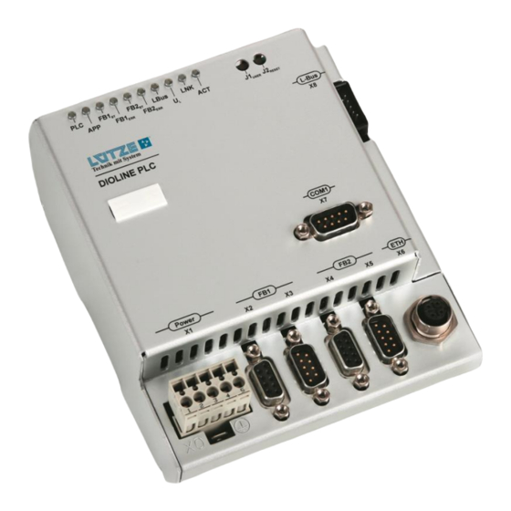
▪ DIOLINE PLC Product assembly Product assembly Number Description LED diagnosis display User and reset button L-Bus Interface RS 232 Interface Ethernet Interface Fieldbus 2 – Profbus Master Interface outgoing Fieldbus 2 – Profibus Master Interface incoming Fieldbus 1 – MVB Interface outgoing Fieldbus 1 –... -
Page 20: Led Display
▪ DIOLINE PLC Product assembly LED display Color State Description yellow 0.1s on/0.9s off PLC is ready – no project 0.5s on/0.5s off PLC is in STOP mode 0.8s on/0.2s off PLC reports an error PLC is in RUN mode... - Page 21 ▪ DIOLINE PLC Product assembly Color State Description – Profibus Communication to all slaves has been interrupted or another serious error has occurred. In redundant mode: the active master was not found Communication to at least flashing one slave is interrupted...
-
Page 22: Technical Data
▪ DIOLINE PLC Technical data Technical data Mechanics Dimensions 123x141.5x64.1 mm (wxhxd) Weight 0.550kg/piece Housing Aluminum, anodized surface Mounting Top Hat Rail TS 35 7.5 mm Electrical characteristics Power Supply DC 24 V (voltage range 16.8-30 V) Ripple Max. 10 %... - Page 23 ▪ DIOLINE PLC Technical data Interfaces Diagnosis & Update ▪ Ethernet 100Base TX ▪ SD Card Slot I/O interface ▪ L-BUS Fieldbus Interfaces ▪ Profibus Master (Fieldbus 2) ▪ MVB (Fieldbus 1) ▪ RS232 Software Operating System Real-Time Operating System rcX...
- Page 24 ▪ DIOLINE PLC Technical data Environmental condition Operating -40°C to +70°C Temperature Storage Temperature -40°C to +85°C Relative Humidity 100% short time condensation allowed International IP20 Protection Class (IP) Standards EN 50155 Electronic Equipment on Railway Vehicles EN 50121-3-2 Electromagnetic Compatibility...
-
Page 25: Mounting
▪ DIOLINE PLC Mounting Mounting Risk of injury by electric current Persons can be injured by electric current and the product can be damaged. De- energize the system before mounting. Mount the product with a distance of 5 mm minimum to other products to provide good air conditions. -
Page 26: Mounting Options
▪ DIOLINE PLC Mounting Mounting options The DIOLINE PLC can be mounted on a top-hat rail. Following mounting options are possible: ▪ horizontal ▪ vertical ▪ across... -
Page 27: Initial Operation - Hardware
▪ DIOLINE PLC Initial operation – hardware Initial operation – hardware Initial commissioning must be carried out by electrically skilled personnel. It is possible to read four discrete signals directly through the PLC using the local digital inputs. It is also possible to select an MVB configuration file with several profiles using the digital inputs when the PLC first starts up. - Page 28 ▪ DIOLINE PLC Initial operation – hardware 1. Switch off the power. 2. Connect the devices regarding the pin assignment: Connector Signal Description 24 V Supply voltage 24 V Supply voltage Protective earth 0 V Supply voltage 0 V Supply voltage 3.
-
Page 29: L-Bus Interface
▪ DIOLINE PLC Initial operation – hardware 10.2 L-Bus interface Switch off the power supply when connecting or disconnecting the I/O modules Failure to do so may damage the entire system. Hot plugging is not supported by the system. Connect a maximum of 10 I/O modules via the L-bus interface. - Page 30 ▪ DIOLINE PLC Initial operation – hardware 3. Connect the devices regarding the pin as- signment. Con- Signal Description nector 24 V Supply voltage 24 V Supply voltage 0 V potential /L_Bus_RESET Module reset BUS_END Identifier bus end OUT_OK Data confirmation...
- Page 31 ▪ DIOLINE PLC Initial operation – hardware 5. Switch on the power. Fig. 6: PLC with connected I/O modules 6. The LB LED is green. The device is ready.
-
Page 32: Serial Interface
▪ DIOLINE PLC Initial operation – hardware 10.3 Serial interface It is not possible to program or parameterize the PLC via the serial interface RS232. The serial interface can be programmed by MULTIPROG and should be used for diagnosis only. The access to the serial interface is only possible by the user-specific application software. -
Page 33: Sd Card Slot
▪ DIOLINE PLC Initial operation – hardware 10.4 SD card slot The PLC comes with a SD card slot. You can find the slot for the card on the left side of the PLC housing. The slot is covered by a foil to protect the PLC from incoming dust and other environmental influences. -
Page 34: 1Changing The Sd Card
▪ DIOLINE PLC Initial operation – hardware 10.4.1 Changing the SD card If you replace an old SD card with a new one, make sure that it is a special industrial card specified by Lütze. To change the SD card, proceed as follows: 1. -
Page 35: Ethernet Interface
▪ DIOLINE PLC Initial operation – hardware 10.5 Ethernet interface The Ethernet interface is used for communication between PLC and PC. Via this interface the PLC can be programmed, visualized, parameterized and debugged in the application software. The Ethernet interface is hot plugging compatible. -
Page 36: Fieldbus 1 Interface - Mvb(Emd)
▪ DIOLINE PLC Fieldbus 1 Interface – MVB(EMD) 10.6 Fieldbus 1 Interface – MVB(EMD) The PLC supports the MVB Slave mode only. The MVB is a special made field bus for trains to transmit commands. It is a part of the train communication network and can also be used with the wire train bus. -
Page 37: Fieldbus 2 Interface - Profibus Master
▪ DIOLINE PLC Fieldbus 2 Interface – Profibus Master 10.7 Fieldbus 2 Interface – Profibus Master 1. Switch off the power. 2. Connect the PLC with the devices Signal Description over a suitable bus cable. Not connected Not connected RxD/... -
Page 38: Initial Operation - Software
▪ DIOLINE PLC Initial operation – software Initial operation – software For more information on the initial operation of the software, refer to the “Application Manual“. -
Page 39: Operation
▪ DIOLINE PLC Operation Operation 12.1 Hardware architecture The Parallel Flash Disk has a size of 2 MB. Saves diagnostic data permanently, e.g. errors. Watchdog The watchdog monitors the PLC and is controlled via the function block IKS Digital Monitor. If the watchdog does not receive a request or a signal from the PLC after 2 seconds, it will restart the PLC. - Page 40 ▪ DIOLINE PLC Operation UART1 Extended interface RSBUS or RS485 bus. SDRAM (Synchronous Dynamic Random Access Memory) The memory of the PLC with a size of 32 MB. For the project software <1 MB can be used, because of the PLC performance.
-
Page 41: Memory Architecture (Non-Volatile Memory)
▪ DIOLINE PLC Operation 12.2 Memory architecture (non-volatile memory) SD Card For saving project specific user files. FRAM For saving retain data. Because of data mirroring 4 kB are effective available. The smallest unit of the FRAM are 4 byte. The FRAM can be triggered by a function block or by setting a time value in the PROCONOS.INI. -
Page 42: 1Ram Architecture (Volatile Memory)
▪ DIOLINE PLC Operation 12.2.1 RAM architecture (volatile memory) The RAM is the main memory of the PLC. Every PLC has a memory of 32 MB. The RAM is divided in 5 different sizes and functionalities: PROCONOS RAM For processing the program code 1 MB is provided. The amount of free memory can be seen in the control dialog>program memory. - Page 43 ▪ DIOLINE PLC Operation OS-RAM Is used for different Operating System Tasks. 2. Buffer The second Buffer is reserved for further operation.
-
Page 44: Maintenance
▪ DIOLINE PLC Maintenance Maintenance 13.1 Maintenance software For more information on the firmware updates and configuration of the software, refer to the “Application Manual“. -
Page 45: Demounting
▪ DIOLINE PLC Demounting Demounting 1. Push the PLC upwards. 2. Pull the PLC off the top hat rail. 3. Press the PLC down and remove the PLC from the rail. -
Page 46: Shutdown And Disposal
▪ DIOLINE PLC Shutdown and disposal Shutdown and disposal Observe the valid environmental regulations of your country for the final shutdown and disposal. Disassemble the device and completely dismantle it before disposal. Dispose of electric parts in line with the regulation for Waste of Electrical and Electronic Equipment (WEEE DE 65543672). -
Page 47: Service
▪ DIOLINE PLC Service Service If you have any further questions regarding the product or our repair service, please contact us at: Lütze Transportation GmbH Bruckwiesenstraße17-19 71384 Weinstadt Germany Phone: +49 (0) 7151 6053-545 Fax: +49 (0) 7171 6053-6545 E-Mail: Sales.Transportation@luetze.de... -
Page 48: Revision Of The Document
▪ DIOLINE PLC Revision of the document Revision of the document Version Revision Date First draft of the document 11/25/2020 Release of the document 02/02/2021 Completely revised document structure 03/01/2023...
Need help?
Do you have a question about the DIOLINE PLC and is the answer not in the manual?
Questions and answers