Lütze DIOLINE PLC Operating Instructions Manual
Hide thumbs
Also See for DIOLINE PLC:
- Operating instructions manual (141 pages) ,
- Operating instructions manual (49 pages)
Table of Contents
Advertisement
Quick Links
Advertisement
Table of Contents

Related Manuals for Lütze DIOLINE PLC


Summary of Contents for Lütze DIOLINE PLC
- Page 1 Operating Instructions DIOLINE PLC Part-No. 746050/746051 Version 01...
- Page 2 DIOLINE PLC - Profibus - Operating instructions The company Lütze Transportation GmbH reserves the right to make changes to its products in the interest of technical development. These changes are not necessarily documented in each individual case. This manual and the information contained herein have been compiled with due care. However, the company Lütze Transportation GmbH accepts no liability for printing or other errors or resulting...
-
Page 3: Table Of Contents
4.3 Software options ..................... 13 4.4 System overview ..................... 14 4.5 Field of application ..................15 4.5.1 All DIOLINE PLC operating instructions in overview ............16 Technical Data ................17 Transport and storing ..............19 6.1 Scope of delivery .................... 19 Product assembly .............. - Page 4 DIOLINE PLC - Profibus - Operating instructions 9.3 Serial Interface ....................26 9.4 SD Card slot ....................27 9.4.1 Changing the SD card ..................... 27 9.5 Ethernet interfaces ..................29 9.6 Fieldbus 1 – MVB .................... 30 9.7 Fieldbus 2 Interface – Profibus ............... 32 Initial Operation –...
-
Page 5: Introduction
DIOLINE PLC - Profibus - Operating instructions 1 Introduction This manual is a component of the product: DIOLONE PLC. These instructions must be read and understood before installing, operating, maintaining or dismantling the device. It contains important information about the handling and safety. -
Page 6: General Information
DIOLINE PLC - Profibus - Operating instructions 2 General Information 2.1 Symbol Description The manual contains several safety messages. Each safety message contains a defined signal word and a color. The color and the word are referring to an alert level. There are 4 levels. The safety messages point out hazardous situations and give information to avoid those. -
Page 7: Related Documents
DIOLINE PLC - Profibus - Operating instructions 2.4 Related Documents The programming environment of the DIOLINE PLC is a product of the company PHOENIX CONTACT Software GmbH and Hilscher. The companies are responsible for the documentation and the compliance of standards. This document contains short parts of the software documentation. -
Page 8: Safety
• as a high capacity gateway for the realization of different vehicle specific bus signals. Use the DIOLINE PLC just for the listed cases and just with external devices recommended and allowed by Lütze Transportation GmbH. 3.3 Recipients The operating manual addresses planers, project manager and programmers. -
Page 9: Responsibility Of The Operator
DIOLINE PLC - Profibus - Operating instructions 3.5 Responsibility of the operator The operator is obligate by the law of occupational safety, if the product is used in a commercial field. • The operator is responsible to train the employees and to inform himself about the industrial safety regulation. -
Page 10: Safety Arrangement
DIOLINE PLC - Profibus - Operating instructions 3.9 Safety Arrangement Do not bypass protection equipment and safety arrangements. The product can be damaged by overvoltage and electric shocks are possible. 3.10 Special Safety Messages Use a nominal operating voltage of 24 Volts. The lower (16.8 Volts) and upper (30 Volts) threshold voltage is given in the technical data. -
Page 11: Product Overview
The software can handle multiuser projects over a network access. There are several options regarding the interfaces and software. The DIOLINE PLC can be used to automate simple vehicles, as a subsystem controller or as a powerful gateway to implement various vehicle-specific bus signals. -
Page 12: Hardware Options
DIOLINE PLC - Profibus - Operating instructions 4.2 Hardware options Part. - No. Option/Product Type 746026 DIOLINE PLC, COM-COM DL-PLC-COM-COM-LUE 746027 DIOLINE PLC, COM-CAN DL-PLC-COM-CAN-LUE 746028 DIOLINE PLC, MVB-CAN DL-PLC-MVB/EMD-CAN-LUE 746028.02 DIOLINE PLC, MCB-CAN-DI DL-PLC-MVB-CAN-DI-4-ALS 746029 DIOLINE PLC, COM-RS485 DL-PLC-COM-NFB-RS485-LUE... -
Page 13: Software Options
DIOLINE PLC - Profibus - Operating instructions 4.3 Software options Part-No. Type/Option Description 746090 DR-PC2-SW-KWS DIORAILPC SOFTWARE 4.6 MULTIPROG Suite+ - MULTIPROG Pro+ for IEC61131 programming (also contains the MAS machine sequence language) - SYCON.net for the bus configuration - ProVisIT for visualization and - SYCON.net for interconnecting PROFInet components... -
Page 14: System Overview
DIOLINE PLC - Profibus - Operating instructions 4.4 System overview The DIOLINE PLC can be integrated in the product line of the DIOLINE 20 automating system as follows. The DIOLINE product line contains modular components. A unit consists of a controller with an integrated CPU and an extension module. -
Page 15: Field Of Application
Unmanaged Ethernet Switch 4.5 Field of application The DIOLINE PLC is designed for use in railway vehicles. It can be used for automation of simple vehicles, as subsystems or for high-capacity gateways to transfer vehicle specific bus signals. The graphic below shows possible application areas in trains:... -
Page 16: All Dioline Plc Operating Instructions In Overview
DIOLINE PLC - Profibus - Operating instructions Fig. 3: Example Application 2: Fire Protection Control Unit 4.5.1 All DIOLINE PLC operating instructions in overview A list with an overview and links to the respective operating instructions can be found here. -
Page 17: Technical Data
DIOLINE PLC - Profibus - Operating instructions 5 Technical Data Mechanics Dimensions 123x141.5x64.1 mm (wxhxd) Weight 0.550kg/piece Housing Aluminium, anodized surface Mounting Top Hat Rail TS 35 7.5 mm Electrical Characteristics Power Supply DC 24 V (voltage range 16.8-30 V) Ripple Max. - Page 18 DIOLINE PLC - Profibus - Operating instructions Run up time state: “ready” after switching on the power supply <15s Boot time Memory Internal Serial Flash 4 MB Serial Flash Memory Memory Internal Working 32 MB SDRAM Memory Internal FRAM 4 kB...
-
Page 19: Transport And Storing
But try to store and transport it in a dust free environment to avoid damages of the PLC. 6.1 Scope of delivery The software for the DIOLINE PLC can be downloaded in the internet. The Link and the password will be sent by e-mail. •... -
Page 20: Product Assembly
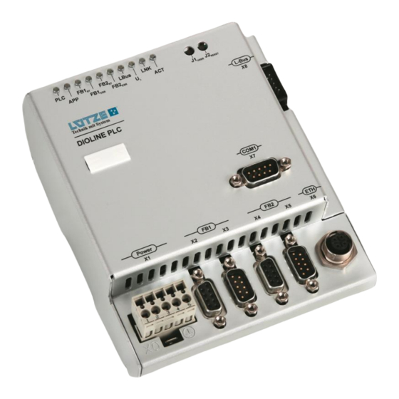
DIOLINE PLC - Profibus - Operating instructions 7 Product assembly LED-Diagnosis Display User and Reset Button L-Bus Interface RS 232 Interface Ethernet Interface Fieldbus 2 – Profibus Fieldbus 2 – Profibus Fieldbus 1 – MVB Interface outgoing Fieldbus 1 – MVB Interface incoming... -
Page 21: Led Display
DIOLINE PLC - Profibus - Operating instructions 7.1 LED Display Color Description ⚫ Operating mode of PLC yellow see also chapter "9.1.1 PLC LED status" ⚫/⚫ Function programmable in user program red/green ⚫ –MVB MVB status (programmable) green ⚫ –MVB MVB error (programmable) ⚫... -
Page 22: Mounting
DIOLINE PLC - Profibus - Operating instructions 8 Mounting Risk of injury by electric current. Persons can be injured by electric current and the product can be damaged. De-energize the system before mounting. Mount the product with a distance of 5 mm minimum to other products to provide good air conditions. -
Page 23: Initial Operation - Hardware
DIOLINE PLC - Profibus - Operating instructions 9 Initial Operation – Hardware The initial operation has to be done by expert employees. 9.1 Power Supply Short circuits and electric shocks by wrong voltage application and wrong wiring. Switch off the power of the whole system before wiring. Make sure that the connectors are wired correctly before switching on the power. -
Page 24: Plc Led Status
0.8s on / 0.2s off For possible error solutions, see chapter "Error treatment". This can be found in the DIOLINE PLC application manual in chapter “11. Error treatment”. If problems are still occurring, please contact Lütze Transportation GmbH. 9.2 L-Bus – interface The L-Bus interface is for connecting DIOLINE20 I/O modules. - Page 25 DIOLINE PLC - Profibus - Operating instructions Signal Description 2. Mind the pin assignment 24 V Supply Voltage 24 V Supply Voltage 0 V Potential /L_BUS_ Module Reset RESET BUS_END Identifier Bus End OUT_OK Data Confirmation SDIN Receiving Serial Data...
-
Page 26: Serial Interface
DIOLINE PLC - Profibus - Operating instructions 9.3 Serial Interface The serial interface can be programmed by MULTIPROG and should only be used for diagnosis. It is not possible to program or parameterize the PLC over the serial interface RS232. The serial Interface can be programmed out of MULTIPROG. -
Page 27: Sd Card Slot
DIOLINE PLC - Profibus - Operating instructions 9.4 SD Card slot The PLC comes with a SD card slot. You can find the slot for the card on the left side of the PLC housing. The slot is covered by a foil to protect the PLC from incoming dust and other environmental influences. - Page 28 DIOLINE PLC - Profibus - Operating instructions 1. Pull out the card by using tweezers. See the pictures. 2. Put in the new card by pushing the card in the slot as far as it will go.
-
Page 29: Ethernet Interfaces
DIOLINE PLC - Profibus - Operating instructions 9.5 Ethernet interfaces The Ethernet interface is for the communication between PLC and PC. Over this interface the PLC can be programmed, visualized, parametrized and debugged in the application software. The Ethernet interface is hot plugging compatible. There is no need to switch off the power when connecting or disconnecting the Ethernet interface. -
Page 30: Fieldbus 1 - Mvb
DIOLINE PLC - Profibus - Operating instructions 9.6 Fieldbus 1 – MVB The PLC supports the MVB Slave mode only. The MVB is a special made field bus for trains to transmit commands. It is a part of the train communication network and can also be used with the wire train bus. - Page 31 DIOLINE PLC - Profibus - Operating instructions The LEDs for the MVB can be configured by the function block “MVBInfo”, see chapter "4.5.2.2 MVB Function Blocks" in the DIOLINE PLC application manual.
-
Page 32: Fieldbus 2 Interface - Profibus
DIOLINE PLC - Profibus - Operating instructions 9.7 Fieldbus 2 Interface – Profibus 1. Switch off the power. X4/X5 Description 2. Connect the PLC with the devices over a suitable bus cable. Not connected (NC) Not connected (NC) RxD/TxD-P Send/receive data;... -
Page 33: Initial Operation - Software
DIOLINE PLC - Profibus - Operating instructions 10 Initial Operation – Software To commission the software, follow the steps in chapter “5. Initial Operation – Software” of the DIOLINE PLC application manual. -
Page 34: Operation
DIOLINE PLC - Profibus - Operating instructions 11 Operation 11.1 Hardware Architecture The Parallel Flash Disk has a size of 2 MB. Saves diagnosis data permanent, for example errors. Watchdog The watchdog monitors the PLC and is controlled over the function block IKSDigitalMonitor. If the watchdog does not receive a request or a signal from the PLC after 2 seconds, it will restart the PLC. -
Page 35: Software Architecture
DIOLINE PLC - Profibus - Operating instructions Serial Flash The serial flash stores the rcXOperating System, the ProConOS runtime environment, the PLC firmware, the boot project and the configuration files. The data are read from the flash memory and be written in the SDRAM at the startup of the PLC. -
Page 36: Memory Architecture
DIOLINE PLC - Profibus - Operating instructions Dual Ported Memory This layer is the communication between firmware drivers and functions and the ProConOs runtime environment. Firmware In this layer all driver specific processes for the PLC, fieldbuses and other functionalities are done. -
Page 37: Maintenance
The battery comes with article number 746026, 746027, 746032 and 746034. The DIOLINE PLC contains a real time clock which is driven by a battery. This clock must be maintained in specific intervals with the agreement of Lütze Transportation GmbH. -
Page 38: Demounting
DIOLINE PLC - Profibus - Operating instructions 13 Demounting 1. Push the PLC up. 2. Pull the PLC from the top hat rail. 3. Push the PLC down and take the PLC off the rail. -
Page 39: Final Shutdown And Disposal
DIOLINE PLC - Profibus - Operating instructions 14 Final Shutdown and Disposal Mind the valid environmental standard of your country for the final shutdown and disposal. For the final shutdown the device must be disassembled. Electric Parts must be disposed after the national electronic scrap regulation. -
Page 40: Service
DIOLINE 20 Module Types • Autoexec.bat - Configuration commands and description The chapter "Appendix" can be found in the DIOLINE PLC application manual in chapter “10. Appendix”. 17 Error treatment The chapter "Error treatment" can be found in the DIOLINE PLC... -
Page 41: Revision Of The Document
DIOLINE PLC - Profibus - Operating instructions 18 Revision of the Document Version Revision Date First Draft of the Document 11/25/2020 Release of the Document 02/02/2021... -
Page 42: Glossary
DIOLINE PLC - Profibus - Operating instructions 19 Glossary Add-on works according the CSMAICR (Carriers A module which supplements Hardware Sense Multiple Access/ Collision or Software. In contrast to Plug-in, Resolution) system. existing libraries are used and functions are programmed. - Page 43 DIOLINE PLC - Profibus - Operating instructions Hot Plugging or Hot Swapping. PDO short form for Process Data Change of a system component or Object. module during the runtime. The term "hot Object of the CAN Communication. With swapping" is used according to...
- Page 44 DIOLINE PLC - Profibus - Operating instructions Watchdog also called WDC (Watch Dog Counter). A component of a system which monitors other components. ls usually used in micro controller to avoid a breakdown causes by a software failure. WTB short form for Wire Train Bus.
Need help?
Do you have a question about the DIOLINE PLC and is the answer not in the manual?
Questions and answers