Lütze DIOLINE PLC Operating Instructions Manual
Cos-com
Hide thumbs
Also See for DIOLINE PLC:
- Operating instructions manual (45 pages) ,
- Operating instructions manual (49 pages)
Table of Contents
Advertisement
Quick Links
Advertisement
Table of Contents

Related Manuals for Lütze DIOLINE PLC


Summary of Contents for Lütze DIOLINE PLC
- Page 1 Operating Instructions DIOLINE PLC COS-COM, Part-No. 746032 Version 03...
- Page 2 Lütze Transportation GmbH Bruckwiesenstraße 17-19 D-71384 Weinstadt Tel.: +49 (0) 7151 6053-545 Fax: +49 (0) 7151 6053-6545 Sales.Transportation@luetze.de www.luetze-transportation.com...
-
Page 3: Table Of Contents
▪ DIOLINE PLC Content Content Introduction ....................5 General Information ..................6 Symbol Description ........................ 6 Copyright ..........................6 Disclaim of Liability......................... 6 Related Documents........................ 7 Safety ......................8 Content of the Manual ......................8 Intended Use .......................... 8 Recipients..........................8 Operating Employees...................... - Page 4 ▪ DIOLINE PLC Content 11.2.4 Resetting the TCP/IP Address ..................... 41 11.3 Development Environment System – MULTIPROG............. 42 11.3.1 Creating a MULTIPROG Project ..................42 11.3.2 Ressource Settings ......................44 11.3.3 Function Blocks and Firmware Libraries ................46 11.3.4 ProConOS.INI ........................51 11.3.5...
-
Page 5: Introduction
DIOLINE PLC Introduction Introduction This manual is part of the DIOLINE PLC. It contains important information about the handling and safety. To avoid hazardous situations read the manual before installing the product and using it. Store the manual at a handy place. If selling, renting or in case of a divestiture... -
Page 6: General Information
▪ DIOLINE PLC General Information General Information Symbol Description The manual contains several safety messages. Each safety message contains a defined signal word and a color. The color and the word are referring to an alert level. There are 4 levels. The safety messages point out hazardous situations and give information to avoid those. -
Page 7: Related Documents
General Information Related Documents The programming environment of the DIOLINE PLC is a product of the company KW Software and Hilscher. The companies are responsible for the documentation and the compliance of standards. This document contains short parts of the software documentation. -
Page 8: Safety
▪ as a high capacity gateway for the realization of different vehicle specific bus signals Use the DIOLINE PLC just for the listed cases and just with external devices recommended and allowed by Lütze Transportation GmbH. Recipients The operating manual adresses planers, project manager and programmers. It also adresses the operating employees which are responsible for the initial operation, the operating and for the maintenance of the products and systems. -
Page 9: Responsibility Of The Operator
▪ DIOLINE PLC Safety Responsibility of the Operator The operator is obligate by the law of occupational safety, if the product is used in a commercial field. ▪ The operator is responsible to train the employees and to inform himself about the industrial safety regulation. -
Page 10: Reconstruction And Modifications Of The Product
▪ DIOLINE PLC Safety Reconstruction and Modifications of the Product Reconstructions and modifications of the product can cause property damages or personal injuries. Do not reconstruct or modify the product if the manufacturer does not allow it explicit in writing. -
Page 11: Product Overview
Product Overview Product Overview Product Description The DIOLINE PLC is a programmable compact controller in the automation system DIOLINE20. The product is based on a high-performance ARM = Microprocessor (Advanced Risk Machine). It is possible to connect several I/O modules over the L-Bus interface. The L-Bus is a Lütze invention. The product can provide up to 4 bus interfaces. -
Page 12: Software Options
▪ DIOLINE PLC Product Overview RS485 Two Wire Serial Bus RSBUS One Wire Serial Bus No Field Bus Software Options Option Description Item Number DR-PC-SW-KWS KW MULTIPROG Development 746090 Suite+ V 4.8 ▪ Multiprog development environment ▪ IEC61131 Editor ▪... -
Page 13: System Overview
DIOLINE PLC Product Overview System Overview The DIOLINE PLC can be integrated in the product line of the DIOLINE 20 automating system as follows. The DIOLINE product line contains modular components. A unit consists of a controller with an integrated CPU and an extension module. It is possible to connect max. -
Page 14: Field Of Application
Product Overview Field of Application The DIOLINE PLC is designed for use in railway vehicles. It can be used for automation of simple vehicles, as subsystems or for high-capacity gateways to transfer vehicle specific bus signals. The graphic below shows possible application areas in trains: Fig. -
Page 15: Transport And Storing
▪ DIOLINE PLC Transport and Storing Transport and Storing ▪ Protect the product from humidity. Store the product in a dry room between -40 and 85°C. ▪ Make sure that the PLC is safely packaged for transporting, that possible crushes can be absorbed. -
Page 16: Scope Of Delivery
▪ DIOLINE PLC Scope of Delivery Scope of Delivery The software for the DIOLINE PLC can be downloaded in the internet. The Link and the password will be send by e-mail. ▪ DIOLINE PLC ▪ Dummy connector for L-Bus interface ▪... -
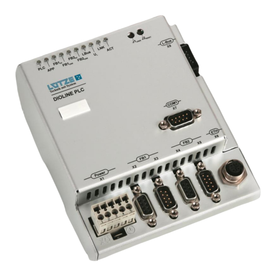
Page 17: Product Assembly
▪ DIOLINE PLC Product Assembly Product Assembly LED-Diagnosis Display User and Reset Button L-Bus Interface RS 232 Interface Ethernet Interface Fieldbus 2 – CANopen Master Interface outgoing X5 Fieldbus 2 – CANopen Master Interface incoming X4 Fieldbus 1 – CANopen Slave outgoing Fieldbus 1 –... -
Page 18: Led Display
▪ DIOLINE PLC Product Assembly LED Display Color State Description yellow 0.1s on/0.9s off PLC is ready – no project 0.5s on/0.5s off PLC is in STOP mode 0.8s on/0.2s off PLC alert an error PLC is in RUN mode... - Page 19 ▪ DIOLINE PLC Product Assembly green Ethernet connection is OK. No Ethernet connection. yellow flashing Ethernet data transfer is No Ethernet data transfer.
-
Page 20: Technical Data
▪ DIOLINE PLC Technical Data Technical Data Mechanics Dimensions 123x141.5x64.1 mm (wxhxd) Weight 0.550kg/piece Housing Aluminum, anodized surface Mounting Top Hat Rail TS 35 7.5 mm Electrical Characteristics Power Supply DC 24 V (voltage range 16.8-30 V) Ripple Max. 10 %... - Page 21 ▪ DIOLINE PLC Technical Data Interfaces ▪ RS232 ▪ Ethernet 100Base TX ▪ SD Card Slot Fieldbus Interfaces ▪ L-BUS ▪ CANopen Software Operating System Real-Time Operating System rcX Controller Software IECX 61131 Soft-PLC ProConOS KW Software Processor ARM9-CPU NetX 500, 32 Bit...
- Page 22 ▪ DIOLINE PLC Technical Data International Protection IP20 Class (IP) Standards EN 50155 Electronic Equipment on Railway Vehicles EN 5021-3-2 Electromagnetic Compability EN 50124-1 Insulation Coordination EN 61373 Vibration and Shock...
-
Page 23: Mounting
2. Push the product a little bit up. 3. Push the product back that it catches the top-hat rail. Mounting Options The DIOLINE PLC can be mounted on a top-hat rail. Following mounting options are possible: ▪ horizontal ▪... -
Page 24: Initial Operation - Hardware
▪ DIOLINE PLC Initial Operation – Hardware Initial Operation – Hardware The initial operation has to be done by expert employees. 10.1 Power Supply Short circuits and electric shocks by wrong voltage application and wrong wiring. Switch off the power of the whole system before wiring. Make sure that the connectors are wired correctly before switching on the power. -
Page 25: L-Bus - Interface
▪ DIOLINE PLC 10.2 L-Bus – Interface The L-Bus interface is for connecting DIOLINE20 I/O modules. The L-Bus, also called Lütze Bus, is a special Bus invented by company Lütze. Switch off the power when connecting or disconnecting the I/O modules. - Page 26 ▪ DIOLINE PLC 3. Connect the DIOLINE 20 I/O Modules over the L-Bus interface. 4. Switch on the power. Fig. 3: L-Bus connector Fig. 4: PLC with connected I/O Modules 5. The LB LED is green. The device is ready.
-
Page 27: Serial Interface
▪ DIOLINE PLC 10.3 Serial Interface The serial interface can be programmed by MULTIPROG and should only be used for diagnosis. It is not possible to program or parameterize the PLC over the serial interface RS232. The serial Interface can be programmed out of MULTIPROG. -
Page 28: Sd Card Slot
▪ DIOLINE PLC 10.4 SD Card Slot The PLC comes with a SD card slot. You can find the slot for the card on the left side of the PLC housing. The slot is covered by a foil to protect the PLC from incoming dust and other environmental influences. -
Page 29: Changing The Sd Card
▪ DIOLINE PLC 10.4.1 Changing the SD Card If changing the SD Card to a new one, make sure that you are using a special industrial card which is specified by Lütze. To change the SD Card follow these steps: 1. -
Page 30: Ethernet Interface
▪ DIOLINE PLC 10.5 Ethernet Interface The Ethernet interface is for the communication between PLC and PC. Over this interface the PLC can be programmed, visualized, parameterized and debugged in the application software. The Ethernet interface is hot plugging compatible. There is no need to switch of the power when connecting or disconnection the Ethernet interface. -
Page 31: Fieldbus 1 Interface - Canopen Master
▪ DIOLINE PLC 10.6 Fieldbus 1 Interface – CANopen Master 1. Switch off the power. Signal Description 2. Connect the PLC with the devices Connector Protective over a suitable bus cable. Housing Earth Not connected CANL CAN-Signal DGND CAN-Signal ground... -
Page 32: Fieldbus 2 Interface - Canopen Slave
▪ DIOLINE PLC 10.7 Fieldbus 2 Interface – CANopen Slave 1. Switch off the power. 2. Connect the PLC with the devices Signal Description over a suitable bus cable. Connector Protective Housing Earth Not connected CANL CAN-Signal DGND CAN-Signal ground... -
Page 33: Initial Operation - Software
▪ DIOLINE PLC Initial Operation – Software Initial Operation – Software 1. Download the software under the sent link. The software has to be requested at Lütze. Install all software package into one and the same directory. Otherwise the software package does not work right. -
Page 34: Installation
▪ DIOLINE PLC Initial Operation – Software 11.1 Installation 11.1.1 MULTIPROG Before installing the software mind the system requirements. The MULTIPROG software is an integrated development environment according to the IEC 61131 standard. With the software you program your application software and parameterize the PLC. -
Page 35: Proconos Opc Server
▪ DIOLINE PLC Initial Operation – Software 11.1.2 ProConOS OPC Server The ProConOS OPC Server realizes the communication between PLC and OPC Client. The client is the visualizing program ProVisIT. The data exchange is done by TCP/IP. If using the Multiprog Suite the ProVisIT visualization Software is installed automatically. -
Page 36: Lütze Addons
▪ DIOLINE PLC Initial Operation – Software 11.1.3 Lütze Addons The addons contain functions for the programming system MULTIPROG. The addons implementing necessary resources for embedding the PLC in the integrated development environment. 1. Double click setup Luetze_Addons_V4.0 . 2. The automatic installation assistent starts. -
Page 37: Ip Configuration
▪ DIOLINE PLC Initial Operation – Software 11.2 IP Configuration Mind choosing the same subnet for all communication devices by configuring the subnet mask. Every communication node must have a different IP address. The standard IP address for the PLC is 192.168.0.215 and the standard subnet mask is 255.255.255.0. - Page 38 ▪ DIOLINE PLC Initial Operation – Software Following window appears: 6. Double click Internet protocol (TCP/ IP). Do not use the PLC IP address. 7. Choose Using following IP address. 8. Type in an IP address. For example: 192.168.0.10 9. Type in a subnet mask: 255.255.255.0...
-
Page 39: Communication Check
▪ DIOLINE PLC Initial Operation – Software 11.2.2 Communication Check To program and monitor the PLC with MULTIPROG make sure, that the communication between PC and PLC is working. Proceed as follows: 1. Open Windows Start Menu > Run. Following window appears: 2. -
Page 40: Plc Ip Address
▪ DIOLINE PLC Initial Operation – Software 11.2.3 PLC IP Address Mind choosing the same subnet for all communication devices by configuring the subnet mask. Every communication node must have a different IP address. The standard IP address for the PLC is 192.168.0.215 and the standard subnet mask is 255.255.255.0. -
Page 41: Resetting The Tcp/Ip Address
▪ DIOLINE PLC Initial Operation – Software 11.2.4 Resetting the TCP/IP Address The resetting of the TCP/IP is just possible during the start of the PLC. The resetting of the TCP/IP is not possible if an SD card with the autoexec.bat is inserted. -
Page 42: Development Environment System - Multiprog
▪ DIOLINE PLC Initial Operation – Software 11.3 Development Environment System – MULTIPROG 11.3.1 Creating a MULTIPROG Project To program the PLC, it is necessary to create a project with the MULTIPROG software. To create a project use the project assistant. - Page 43 ▪ DIOLINE PLC Initial Operation – Software Step 2 Project Assistant 1. Type in any name for the first program organization Unit (POU) in the field Name of POU. 2. Choose a language for the POU. 3. Click NEXT. Step 3 Project Assistant 1.
-
Page 44: Ressource Settings
▪ DIOLINE PLC Initial Operation – Software 11.3.2 Ressource Settings In the resource settings you configure MULTIPROG specific parameters for the communication between the PLC and PC. 1. Start MULTIPROG. 2. Click with the right mouse button on Ressource:PROCONOS in the Project tree window. - Page 45 ▪ DIOLINE PLC Initial Operation – Software Other options are: ▪ Stack check on PLC If activated the stack will be checked for overflows. A possibility of a decreased operation speed can occur. A higher security is provided. ▪ Generate bootproject during...
-
Page 46: Function Blocks And Firmware Libraries
▪ DIOLINE PLC Initial Operation – Software 11.3.3 Function Blocks and Firmware Libraries Function blocks can be inserted from the firmware or user libraries in MULTIPROG. There is also the option to program your own function blocks. For further information to program your own function blocks, read the KW Software MULTIPROG manual. - Page 47 ▪ DIOLINE PLC Initial Operation – Software 7. In the project tree menu double click on the POU in which the function block should be insert. 8. Click on the work sheet. A cross will appear. 9. In the toolbar click On the right side the menu Edit Wizard appears.
- Page 48 ▪ DIOLINE PLC Initial Operation – Software Adding the POU to the Task 1. Click right in the project tree window on any task. 2. Choose Insert. 3. Click Program Instance. The window Insert appears. 4. Define a name for the program instance.
- Page 49 ▪ DIOLINE PLC Initial Operation – Software 11.3.3.1 Hardware Watchdog – IKSMonitor Digital The function block controls the hardware watch dog. At every execution a signal is sent to the hardware watch dog. This signalizes the correct operation of the PLC.
- Page 50 ▪ DIOLINE PLC Initial Operation – Software 11.3.3.2 IKSMonitor Analog Shows all measured voltage values by the controller and the version of the PLC firmware and the MAC address of the ethernet interface. Output Description Type Supply_5 Displays the analog power supply of 5 V.
-
Page 51: Proconos.ini
▪ DIOLINE PLC Initial Operation – Software 11.3.4 ProConOS.INI The ProConOS.INI is an initialization file which contains application specific settings for following parameters: ▪ CANopen Slave ▪ CAN2.0 ▪ Serial Interface 1 and 2 ▪ Parallel Flashdisk ▪ ▪ Retain Data Storing The specific settings for the ProConOS.INI can be found in the different... -
Page 52: Variables
▪ DIOLINE PLC Initial Operation – Software 11.3.5 Variables The valid area of the variables is local or global. The variables are declared by the location, type and the name. Following types are supported by MULTIPROG: Type Description Range length... - Page 53 ▪ DIOLINE PLC Initial Operation – Software 11.3.5.1 Globale Variables The global variables can be used in the whole project. The variable has to be declared as VAR_GLOBAL in the global variable datasheet. In the single POUs, where the variable is used, it has to be declared as VAR_EXTERNAL. To allocate global variables proceed as follows: 1.
- Page 54 ▪ DIOLINE PLC Initial Operation – Software 6. Set the properties: ▪ Name Type in a unique name for the variable. ▪ Type Choose a type for the variables. The different types are listed in the chapter “Variables“. ▪ Usage The usage will be automatically set to VAR_GLOBAL.
- Page 55 ▪ DIOLINE PLC Initial Operation – Software ▪ %IW 1 The first number adresses the first and second byte at the same time. ▪ Init Type in a start value for the variable. Depending on the data type. ▪ Retain The marked variables are defined with the memory cycle time in the PROCONOS.INI or by triggering the WriteRetain function block.
- Page 56 ▪ DIOLINE PLC Initial Operation – Software 11.3.5.2 Local Variables Local Variables can just be declared in the POUs datasheets. To allocate local variables proceed as follows: 1. Double click Global Variable of the selected POU in the project tree.
- Page 57 ▪ DIOLINE PLC Initial Operation – Software 11.3.5.3 Retain Variables All variables which are marked with RETAIN can be stored in the FRAM. The storing cycle time can be configured in the ProConOS.INI. ProConOS.INI Cyclic storage interval in ms. [Retain]...
-
Page 58: Configuration Of The Fieldbusses And Other Interfaces
▪ DIOLINE PLC Initial Operation – Software 11.4 Configuration of the Fieldbusses and other Interfaces 11.4.1 L-Bus Configuration To control the DIOLINE20 modules, which are connect via the L-Bus, it is necessary to configure the driver of the L-Bus. The L-Bus driver is byte organized. Every L-Bus module has a predefined amount of input and output bytes. - Page 59 ▪ DIOLINE PLC Initial Operation – Software The window Adding I/O group appears: 3. Type in the name of the interface. 4. Choose the task of the L-Bus driver in which it should be processed The driver should not run in the Default task. It can cause data inconsistency.
- Page 60 ▪ DIOLINE PLC Initial Operation – Software Configuration OUTPUT 1. Click on the register OUTPUT, 2. Click Add to add an Output. The window Adding I/O group appears: 3. Type in the name of the interface. 4. Choose the task of the L-Bus driver in which it should be processed.
- Page 61 ▪ DIOLINE PLC Initial Operation – Software 11.4.1.2 L-Bus Function Blocks The embedding of following function blocks from the IKSL-Bus library is necessary. L-BusInfo The function block displays the state of the L-Bus interface and is used for the parameterization.
- Page 62 ▪ DIOLINE PLC Initial Operation – Software AverageCycleTime Displays the average time of the 10 last TIME cycles. SlaveCount Displays the number of the connected DIOLINE20 modules. Signalizes that the L-Bus is initialized BOOL correct. The L-Bus is running. Stop Signalizes that the L-Bus is stopped.
- Page 63 ▪ DIOLINE PLC Initial Operation – Software Output Description Type Type Displays the type ID. For a ID list see chapter "DIOLINE 20 Module Types" on page 135. Error Displays an error number. For the description of error number, see chapter "Error Treatment"...
-
Page 64: Sd Card Configuration
▪ DIOLINE PLC 11.4.2 SD Card Configuration Make sure that you are using a special industrial card which is specified by Lütze. If using the L-Bus interface and the SD-Card at the same time there might be some delays in the data transfer of the L-Bus. The L-Bus and SD card sharing the SPI interface. - Page 65 ▪ DIOLINE PLC Output Description Type Done Is TRUE if the data could be read correctly, BOOL otherwise the output will be FALSE. LengthRead Displays the number of the characters which were UDINT read. Buffer The received data are stored in the buffer.
- Page 66 ▪ DIOLINE PLC Output Description Type Done Is TRUE if the file could be closed correctly, BOOL otherwise the output will be FALSE. Error Is TRUE if an error occurred, otherwise the output BOOL will be FALSE. ErrorID Displays an error number. For an explanation of UINT the error numbers see chapter "FILE_CLOSE"...
-
Page 67: Pfd - Parallel Flash Disk
▪ DIOLINE PLC 11.4.3 PFD – Parallel Flash Disk The Parallel Flash Disk saves diagnostic data, which are defined by the user. The memory is permanent. It can save a defined amount of data. The PFD is organized in two superior data sections. - Page 68 ▪ DIOLINE PLC 11.4.3.1 Saving Modes Ring Mode The flash memory is physically organized by pages. Every page has a size of 128 kB. If deleting data the flash will always delete the minimal amount of one page (128 kB).
- Page 69 ▪ DIOLINE PLC NrEntriesMax1 Displays the maximum quantity of slots in DINT section 1. NrEntriesUsed1 Displays the number of used slots in section 1. DINT NrEntriesDefect1 Displays the number of defect slots in section DINT Status2 Displays the current state of section 2.
- Page 70 ▪ DIOLINE PLC PFDReadByID With the function block it is possible to read the slots by the slot ID. The slot ID is assigned for every written slot. An ID is assigned unique and once. If a section is been deleted the counting of the ID starts all over again.
- Page 71 ▪ DIOLINE PLC Start If a 0 is pending the reading will start with the oldest DINT entry. If a 1 is pending the reading will start with the second oldest entry. If a -1 is pending the reading will start with the newest entry.
- Page 72 ▪ DIOLINE PLC Output Description Type Done At the end of the copying process the input will be BOOL TRUE. Even if an error occurs. Error Displays an error number. For an explanation of the error numbers see chapter "Error Messages of the...
-
Page 73: Real Time Clock Configuration
▪ DIOLINE PLC 11.4.4 Real Time Clock Configuration The real time clock works with a battery. If the power of the system is switched off, the clock is still running. The real time clock uses the I2C bus when progressing and while setting. - Page 74 ▪ DIOLINE PLC SetDateTime The function block sets the time with the values of the system. Following ranges are valid: Input Description Type Year Defines the year, greater than 2000. Month Defines the month between 1 and 12. Defines the day between 1 and 31.
- Page 75 ▪ DIOLINE PLC 11.4.4.2 Using RTC (Real Time Clock) and FRAM If you are using the Real Time Clock and the FRAM at the same time it can cause timing constraints. The RTC and FRAM are using the same I2C interface.
-
Page 76: Canopen Master Configuration
▪ DIOLINE PLC 11.4.5 CANopen Master Configuration 11.4.5.1 SYCON.NET The Configuration of the CANopen network must be set in the SYCON configurator. The Tool is implemented in a seperate workspace in MULTIPROG. EDS File An EDS File (Electronic Datasheet) is needed for every device on the CANopen Bus. - Page 77 CANopen Master. Adding a Master The DIOLINE PLC is the Master. 1. In the menu tree click on the + infront of the folder Hilscher. 2. Click on the + of the subfolder Master.
- Page 78 ▪ DIOLINE PLC Adding a Slave In this example the buscoupler DIOLINE 20 CANopen is the slave. Before adding the slave to the system, set the node ID and the baudrate on the device. Turn the rotary switches with a screwdriver to make the settings.
- Page 79 3. In the navigation area click TCP/IP Driver for netX. Type in the IP address of the DIOLINE PLC in the IP Start Adress column. If the adress is not known, type in a range where the master could be.
- Page 80 ▪ DIOLINE PLC Master Settings 1. Choose Automatically by device for the start of the bus communication. 2. Choose 1000 ms for the application monitoring time. 3. Choose Big Endian for the storage format. 4. Choose 2 byte boundaries for the module alignment.
- Page 81 ▪ DIOLINE PLC 3. If the master should be stopped in case of an error, choose the checkbox stop in case of monitoring errors. Monitoring errors are: Nodeguard and heartbeat errors. The communication will be stopped of all active nodes.
- Page 82 ▪ DIOLINE PLC Node ID Table 1. Click Node ID Table in the navigation area. ▪ All availables nodes in the master are listed. 2. Click the checkbox to activate or deactivate the nodes. In the column Node ID the Node ID for every single slave can be configured.
- Page 83 ▪ DIOLINE PLC Node Boot Up 1. Click Node Boot Up in the navigation area. ▪ It is the Node Boot Up start performance of the master. ▪ If no slaves are available or configured all options under this menu item are deactivated.
- Page 84 ▪ DIOLINE PLC 4. If all datas are parameterized click Apply. A green square with a checkmark and Save operation succeeded appears in the left lower corner of the window. 5. Click OK to close the window. Node Guard Protocol 1.
- Page 85 ▪ DIOLINE PLC The profiledata cannot changed. Special Function Objects ▪ Information of the different telegrams are displayed. The settings/changes has to be made in the master DTM. ▪ The slave can be configured for generating SYNC messages. ▪ The time stamp is no supported at the moment.
- Page 86 ▪ DIOLINE PLC This values are defined in the EDS file. ▪ If clicking any cell of the table the values are shown in the text fields: ▪Display mode (decimal or hexadecimal). ▪The current configured value. ▪The default value. ▪The data type which displays the minimum and maximum values.
- Page 87 ▪ DIOLINE PLC Transmission Mode ▪ synchron acyclic The PDO is transmitted synchron, but acyclic. The transmission mode combines process-controlled and synchron. ▪ synchron cyclic (1-240) The PDO is transmitted with the SYNC telegram. The cyclic time is defined by the set SYNC cycletime multiplied by the parameter of the field Transmission Rate.
- Page 88 ▪ DIOLINE PLC Mapping (Process Data Objects) 1. Choose from the drop-down list Filter PDO Type the mappable objects which should be displayed in the list. ▪ From the drop-down list Object- Directory Array the object array, which should be displayed can be choosen.
- Page 89 ▪ DIOLINE PLC 4. Change the settings again by attaching a new PDO and deleting 5. Click Apply. ▪ By clicking the arrow buttons the attached objects can be scrolled up or down. By clicking the scissors an attachement can be deleted.
- Page 90 ▪ DIOLINE PLC Processdata Mapping To attach the processdata of the PDOs to the project specific (global) MULTIPROG variables follow these steps: 1. Click Processdata Allocation in the tool bar. Following window appears: 2. Click on the + infront of the master in the right menu tree.
- Page 91 ▪ DIOLINE PLC 10.Make a right click on the master again. 11.Choose Driver Parameters. Following window appears: Make following settings: 12.For the Cardnumber type in “0“. PLC specific there is no card in the device. The CANopen Bus is realized by the CPU directly.
- Page 92 ▪ DIOLINE PLC 11.4.5.3 Function Blocks Embed the following function blocks of the firmware library CIFNetX. CIFNetXInfo Monitores the CANopen Bus status. This functional block has to be insert in the same task as the driver in SYCON.Net. Inputs Description...
- Page 93 ▪ DIOLINE PLC CIFNetXDevice This function block monitores one slave. For every slave such a function block has to be insert. Inputs Description Type BoardNo Demand of the Channelnumber. DeviceNo Demand of the COB ID of the monitored CAN subscriber.
- Page 94 ▪ DIOLINE PLC Route Only for internal use of the NETX firmware. Has to be 0. BoardNo Input for the channel number. Start Trigger for starting the functional block. BOOL Output Description Type SendData Handling of the sending data. RecData Handling of the receiving data.
- Page 95 ▪ DIOLINE PLC Output Description Type Output of the compiled sending data for the CIFnetXAsync functional block. CO_Zuweisung_NMT The functional block is for the assignment of the COB ID and NMT commands. The master can change the status of the slave in a network, following status are possible: ▪...
- Page 96 ▪ DIOLINE PLC Reset Communication Reset of the communication. [cs=82H] Stop Remote Node Stopps the communication, except [cs=02H] nodeguarding and heartbeat. Input Description Type NodeID Defines the COB ID of the subscriber. Broadcast if COB ID=0. NMT_Befehl Sets the command for every node.
-
Page 97: Canopen Slave Configuration
▪ DIOLINE PLC 11.4.6 CANopen Slave Configuration ProConOS.INI The settings have to be made if using the CANopen Slave only. If a master has to be configured an EDS file for the slave is available NETX500 CO/COS (NETX500 CO COS.eds) - Page 98 ▪ DIOLINE PLC 9. Click Driver Parameter... 10.The Driver Information of device CIF window appears. 11.Set the channel number under board number. 12.The standard value for the Offset in Dual Port Ram is 0, do not change the value. 13. Set the Timeout.
-
Page 99: Compiling And Loading
▪ DIOLINE PLC 11.5 Compiling and Loading 11.5.1 Download of Configuration Files Following files can be downloaded on the PLC: ▪ ProConOs.INI ▪ TCPIP.CFG ▪ MVBCFG.BIN Follow the steps to download a configuration file: 1. Start MULTIPROG. 2. Create or open a project which can establish a connection to the PLC 3. -
Page 100: Downloading A Multiprog Project
▪ DIOLINE PLC 11.5.2 Downloading a MULTIPROG Project Before downloading the project make sure to download the necessary configuration files and restarting the PLC. In some cases errors can occur. After finishing the programming it is necessary to compile and download the project. - Page 101 ▪ DIOLINE PLC The window Download appears. For the downloading process following options can be set: ▪ Include Bootproject By checking that option the project on the PLC will start automatically after booting. The project is stored in the flash memory. By not checking that option the project is stored in the RAM.
-
Page 102: Deleting The Flashdisk
▪ DIOLINE PLC 11.5.3 Deleting the Flashdisk The flashdisk must be reset manually, if using firmware version 1.72 or higher. Please proceed as follows: 1. Deleting the flashdisk without a configuration file Download the file flashrem.upd on the PLC. Proceed as described in chapter “Download of configuration Files“. -
Page 103: Visualization - Provisit
▪ DIOLINE PLC 11.6 Visualization – ProVisIT The program is implemented in MULTIPROG. It is for machine visualizing. It can communicate with every controller and devices which are configured in the OPC Server. For visualizing with ProVisIt read the MULTIPROG Quick Start Manual. -
Page 104: Operation
▪ DIOLINE PLC Operation Operation 12.1 Hardware Architecture The Parallel Flash Disk has a size of 2 MB. Saves diagnosis data permanent, for example errors. Watchdog The watchdog monitors the PLC and is controlled over the function block IKSDigitalMonitor. If the watchdog does not receive a request or a signal from the PLC after 2 seconds it will restart the PLC. - Page 105 ▪ DIOLINE PLC Operation of the PLC. UART0 Connection of the serial interface RS232. XM2 and XM3 Connection of the fieldbusses. PHY0 and PHY1 Connection of the Ethernet.
-
Page 106: Software Architecture
▪ DIOLINE PLC Operation 12.2 Software Architecture Below the modular structure of the operating system and its gateways are described. rcxOperation System The operating system of the PLC. ProConOS PLC runtime environment. Dual Ported Memory This layer is the communication between firmware drivers and functions and the ProConOs runtime enviroment. -
Page 107: Memory Architecture (Non Volatile Memory)
▪ DIOLINE PLC Operation 12.3 Memory Architecture (non volatile memory) SD Card For saving project sepcific user files. FRAM For saving retain data. Because of data mirroring 4 kB are effective available. The smallest unit of the FRAM are 4 byte. The FRAM can be triggerd by a function block or by setting a time value in the PROCONOS.INI. -
Page 108: Ram Architecture (Volatile Memory)
▪ DIOLINE PLC Operation 12.3.1 RAM Architecture (volatile memory) The RAM is the main memory of the PLC. Every PLC has a memory of 32 MB. The RAM is devided in 5 different sizes and functionalities: PROCONOS RAM For processing the program code 1 MB is provided. The amount of free memory can be seen in the control dialog>program memory. -
Page 109: Configuration Of The Plc Memory Ranges
▪ DIOLINE PLC Operation 12.3.2 Configuration of the PLC Memory Ranges To confiigure the memory ranges start MULTIPROG and proceed as follows: 1. In the projecttree make a right click on Ressource. 2. Choose Settings. The ressource setting dialog appears. - Page 110 ▪ DIOLINE PLC Operation ▪ Reserve per POU It is possible to allocate an defined memory reserve to an POU. For further information read the MULTIPROG online help. Retain Data The described settings for the non retain data are also valid for the retain data.
- Page 111 ▪ DIOLINE PLC Operation The free program memory space for the programm code (POUs) and the free memory space for the Retaindata is shown. Systemdata shows the free amount of memory for systemdata. This memory is not changeable by the user and used for PLC diagnostics.
-
Page 112: Monitoring The Plc Tasks And Cpu Capacity
▪ DIOLINE PLC Operation 12.3.3 Monitoring the PLC tasks and CPU Capacity We recommend that the processing time for the PLC tasks should never be higher than 50 % of the cycle time. It assures that the other 50 % of the CPU capacity can be used for the lower priority tasks. - Page 113 ▪ DIOLINE PLC Operation 8. The window Object types appears. 9. The option Datatypes is chosen. 10.Click OK. 11.Choose the path of the data type file. 12.Click on the filename in the right window. 13.Click OK. The file will appear under Datatypes in the project tree window.
- Page 114 ▪ DIOLINE PLC Operation 16.Click Logical POU in the project tree window. 17.Import the predefined PLC_Diagnostic POU from the Lütze download area. Follow the steps under importing a file. The new POU appears in the project tree window. 18.Implement the new POU in the task.
-
Page 115: L-Bus Performance
▪ DIOLINE PLC Operation 12.3.4 L-Bus Performance The PLC tasks have a higher priority than the communication tasks. The communication tasks cannot be processed until the PLC tasks are done. The two diagrams are showing the data update of the PLC tasks in two different task configurations. -
Page 116: Maintenance Software
▪ DIOLINE PLC Maintenance Software Maintenance Software 13.1 Update Firmware (ProConOs) The update of the firmware can be done by MULTIPROG or the SD card. 13.1.1 Update via MULTIPROG The firmware is saved on the serial flash. To update the firmware, the serial flash has to be transcribed by the new version. - Page 117 ▪ DIOLINE PLC Maintenance Software Following window appears: 9. Choose the file CHECKSUM.upd. 10.Click Download. 11.Click again Download. 12.Choose the file flash.upd. 13.Click Download. If the download is successful the flash process starts. The APP and USER LED are flashing alternatively. The process takes 1.5 minutes.
-
Page 118: Updating The Plc Via The Sd Card
▪ DIOLINE PLC Maintenance Software 13.1.2 Updating the PLC via the SD Card To update the PLC with configuration files, program files or firmware files. For all updating processes a autoexec.bat must be created. It is possible to combine different updating process commands in one autoexec.bat file. - Page 119 ▪ DIOLINE PLC Maintenance Software 13.1.2.1 Updating the Firmware by the SD Card Do not switch off the PLC while the flash process is running. If such a case occurs it is possible that the PLC is not accessable anymore. The PLC has to be sent to Lütze Transportation GmbH.
- Page 120 ▪ DIOLINE PLC Maintenance Software 13.1.2.2 Updating the software via the SD Card The Bootfile.pro cannot be directly created out of MULTIPROG. To get a valid bootfile.pro file it necessary to copy it once from a already updated PLC. This must be done because of a internal code compilation which is proceeded after each download of a bootprojekt via Mulitprog.
- Page 121 ▪ DIOLINE PLC Maintenance Software 13.1.2.3 Updating the PLC configuration files With this process following files can be updated, if needed: ▪ MVBcfg.bin ▪ config.dbm ▪ PROCONOS.ini ▪ TCPIP.cfg The config.dbm cannot be directly created out of MULTIPROG. The config.dbm must always be read out of the PLC.
- Page 122 ▪ DIOLINE PLC Maintenance Software ▪ If an error occurs the LEDs are flashing 5 times (50 ms on, 50 ms off). For example a file to copy does not exist on the PLC or SD card. ▪ It is possible to load all configuration files, the boot project and the firmware update in one step.
-
Page 123: Final Shutdown And Disposal
▪ DIOLINE PLC Final Shutdown and Disposal Final Shutdown and Disposal Mind the valid environmental standard of your country for the final shutdown and disposal. For the final shutdown the device has to be disassembled. Electric Parts must be disposed after the national electronic scrap regulation. You take the responsibility for the shipped article. -
Page 124: Service
▪ DIOLINE PLC Service Service If you have any further questions regarding the product or our repairing service please contact us: Lütze Transportation GmbH Bruckwiesenstraße17-19 71384 Weinstadt Tel.: +49 7151 6053-545 Fax: +49 7171 6053-6545 Sales.Transportation@luetze.de... -
Page 125: Error Treatment
▪ DIOLINE PLC Error Treatment Error Treatment 16.1 Error Messages of the Function blocks 16.1.1 L-BusInfo Error No error No L-Bus component connected Error at the reading of the initialization process Error at the reading if the type coding Error at the number of data for the process image. -
Page 126: Corec And Cosend
▪ DIOLINE PLC Error Treatment Error The parameter “Name” has no valid character order. The name of the signal is not in the MVBCFG file. The type of the signal is not supported. The port for the signals is not available. -
Page 127: Setdatetime
▪ DIOLINE PLC Error Treatment Error The position of number of the sending data is outside the use data. The length of the use data is bigger than the total number of data. The value and structure of the sending data cannot be evaluate. -
Page 128: File_Write
▪ DIOLINE PLC Error Treatment 16.1.7 FILE_WRITE Error No error information available. Invalid file handle. There is not enough memory to write data. The number of characters is bigger than the data buffer. No data could be write. 16.1.8 FILE_CLOSE Error No error information available. -
Page 129: Appendix
▪ DIOLINE PLC Appendix Appendix 17.1 Content of the Firmware Libraries 17.1.1 MVB-IKS Firmware Library Function Block Description MVBInfo Displays the state of the bus and controls the global bus states. MVBPort Displays the characteristics of the port. SinkANTIVALENT Receives an antivalent value from the bus. -
Page 130: Proconos Firmware Library
▪ DIOLINE PLC Appendix Function Block Description SourceBITSET8 Can send a word variable of 8 bit on the MVB bus. SourceBOOL Can send a boolean variable on the MVB bus. SourceCHAR Can send a character on the MVB bus. SourceENUM4 Can send a variable with a max value of 3 on the MVB bus. - Page 131 ▪ DIOLINE PLC Appendix Function Block Description BUF_TO_TIME Copies element data types from a byte stream in a variable, field or in another element. Supports the data type: TIME BUF_TO_UDINT Copies element data types from a byte stream in a variable, field or in another element. Supports...
- Page 132 ▪ DIOLINE PLC Appendix Function Block Description HOT_RESTART Does a hot start. At a hot start the data will not be initialize. MEMCPY Copies data from the data filed in the running system (source data field) in another data field running system (target data field).
- Page 133 ▪ DIOLINE PLC Appendix Function Block Description RD_TIME_BY_SYM Reads the value of the symbolic variables in PDD. The name of the variable is dedicated to a character sequence. Read the value type: TIME RD_UDINT_BY_SYM Reads the value of the symbolic variables in PDD.
- Page 134 ▪ DIOLINE PLC Appendix Function Block Description WR_DWORD_BY_SYM Writes a double word in a variable, which is insert in the PDD. WR_INT_BY_SYM Writes an integer in a variable, which is insert in the PDD. WR_OUTPUT_GROUP Writes a value of the type output in a variable, which is insert in the PDD.
-
Page 135: Dioline 20 Module Types
▪ DIOLINE PLC Appendix 17.2 DIOLINE 20 Module Types Module Type Item Bytes Bytes Current Number Input Output Consumption (hex) L-Bus 8 Bit digital output 746415 90 mA 8 Bit digital output, 746419 10 mA 16 input diagnosis 746420 746414... -
Page 136: Autoexec.bat Commands
▪ DIOLINE PLC Appendix 17.3 Autoexec.bat Commands Command Description copy2sd filename The entered file is copied from the PLC to the SD card. copy2plc filename The entered file is copied from the SD card to the PLC. fwupdate flash.upd The firmware is used for the flashing. -
Page 137: Revision Of The Document
▪ DIOLINE PLC Revision of the Document Revision of the Document Version Revision Date 1.00 Release of the Document 06/14/2012 ▪ Change of version numbering 12/17/2012 ▪ Update chapter Software Maintenance Correction of LED color for the function 05/17/2016 block IKS Monitor Digital... - Page 138 ▪ DIOLINE PLC Glossar Glossar Add-on named first. For example: A module which supplements hour:minute:second Hardware or Software. in contrast to CAN short form for Controller Area Plug-in, existing libraries are used and functions are programmed. Network. A asynchrony serial bus system which...
- Page 139 ▪ DIOLINE PLC Glossar Flash Memory see EPROM Embedding).Originally the name of a standardized software interface. Data exchange between applications in the FW short form for Firmware. field of automation engineering. An integrated software in electronic devices. Most of the time the software is saved on a flash memory.
- Page 140 ▪ DIOLINE PLC Glossar and control information. SDO short form for Service Data Object. Objects of the CAN communication. Protocol data are sent with this objects. STS short form for Sink Time Supervision SYCON.Net A field device Tool (FOT) or device type manager (DTM).
Need help?
Do you have a question about the DIOLINE PLC and is the answer not in the manual?
Questions and answers