
Related Manuals for Kongskilde GXS 2805 P


Summary of Contents for Kongskilde GXS 2805 P
- Page 1 ORIGINAL INSTRUCTIONS - according to Directive 2006/42/EC, Annex I 1.7.4.1 OPERATOR’S MANUAL GXS 2805 P GXS 3205 P Disc Mower Part number 51505889 edition English March 2019...
-
Page 2: Table Of Contents
Contents 1 GENERAL INFORMATION Note to the owner................1-1 Intended use. - Page 3 Parking the unit Disconnection and parking ............. 4-9 5 TRANSPORT OPERATIONS Road transport Transport position .
- Page 4 Every 40 hours Power Take-Off (PTO) - Grease ............7-15 Lubrication chart .
- Page 5 High guide shoe set ............... 10-1 Hydraulic valve block .
-
Page 7: General Information
Directives 2006/42/EC and 2014/30/EU. Always use genuine KONGSKILDE Service Parts or parts that match at least the same quality, reliability and func- tionality as the equivalent original Service Parts when you service and repair your implement and do not modify your implement without a written permission of the manufacturer. - Page 8 KONGSKILDE is not liable for any damage caused by the use of ''non-genuine” parts and accessories. Rely on your authorized dealer to supply you with genuine KONGSKILDE parts only. These parts are covered by our warranty and will give you the best performance.
- Page 9 It is prohibited to carry out any modifications to the implement unless specifically authorized, in writing, by a KONGSKILDE representative. CLEANING YOUR IMPLEMENT When you use a high pressure washer, do not stand too close to the implement and avoid directing the jet at electronic components, electrical connections, breathers, seals, filler caps, and so on.
-
Page 10: Intended Use
1 - GENERAL INFORMATION Intended use KONGSKILDE disc mower can only perform the usual of the implement will depend on the crop, the condition of work in agriculture. Only connect the disc mower to a trac- the field, the ground, and finally the weather. -
Page 11: Prohibited Usage
No parts must be fitted to this implement, which have not Do not use this implement: been released by KONGSKILDE. They might affect the implement operation, safety of the user or other people, 1. To cut grass in park facilities and lawns. -
Page 12: Electro-Magnetic Compatibility (Emc)
• Ensure that each piece of non‐ KONGSKILDE equipment fitted to the machine bears the CE mark. • The maximum power of emission equipment (radio, telephones, etc.) must not exceed the limits imposed by the national authorities of the country where you use the machine. -
Page 13: Manual Scope And Required Training Level
KONGSKILDE during normal operation, routine service, and maintenance. Periodic service consists of activities that are necessary to maintain the expected life of the KONGSKILDE ma- This manual does not contain all the information that re- chine. These activities have defined intervals. - Page 14 1 - GENERAL INFORMATION must demonstrate the ability to operate and service the KONGSKILDE machine in a correct and safe manner.
-
Page 15: Product Identification Number (Pin)
The unit is identified by a serial number. Serial number, model and other specifications can be found on the PIN plate. Provide your KONGSKILDE dealer the model and PIN when you order parts. Record the PIN in the front of this manual for quick refer- ence. -
Page 16: Product Identification
1 - GENERAL INFORMATION Product identification NOTE: Do not remove or change the Product Identifica- tion Number (PIN) plate (1) on the implement. The PIN plate (1) is on the top of the implement. The PIN is also engraves on the chassis at (A) below the PIN plate (1). -
Page 17: Operator's Manual Storage On The Machine
1 - GENERAL INFORMATION Operator's manual storage on the machine Keep this operator's manual protected and accessible on the tractor whenever you transport or operate the imple- ment. 1-11... -
Page 18: Implement Orientation
1 - GENERAL INFORMATION Implement orientation NOTE: To determine the left-hand side and the right-hand side of the implement, stand behind the implement and face the direction of travel during working operation. The following overhead view illustration is a general repre- sentation of the implement. -
Page 19: Safety Information
2 - SAFETY INFORMATION 2 - SAFETY INFORMATION###_2_### Safety rules and signal word definitions Personal safety This is the safety alert symbol. It is used to alert you to potential personal injury hazards. Obey all safety messages that follow this symbol to avoid possible death or injury. Throughout this manual you will find the signal words DANGER, WARNING, and CAUTION followed by special in- structions. -
Page 20: General Recommendations
2 - SAFETY INFORMATION General recommendations Most farm machinery accidents can be avoided by the • Never let the implement run without supervision. observance of a few simple safety precautions. • Always keep a first aid kit handy. • This operator’s manual contains important information •... -
Page 21: Illustrations
2 - SAFETY INFORMATION Illustrations WARNING Illustrations in this manual may show protective shielding open or removed to better illustrate a par- ticular feature or adjustment. Replace all shields before operating the machine. Failure to comply could result in death or serious injury. W0012A NOTE: Some of the illustrations in this manual have been obtained by photographing prototypes. - Page 22 2 - SAFETY INFORMATION Hazardous chemicals 1. If you are exposed to or come in contact with haz- well as the information in this manual when you ser- ardous chemicals you can be seriously injured. vice the machine. The fluids, lubricants, paints, adhesives, coolant, 4.
-
Page 23: Starting Up The Implement Safely
2 - SAFETY INFORMATION Starting up the implement safely Before you attach the implement to the tractor, ensure that Repair immediately a damaged PTO shaft before you the tractor is in good working order and that the brakes work with the implement. are efficient, particularly if you operate on hilly ground. -
Page 24: Traveling On Public Roads
2 - SAFETY INFORMATION Traveling on public roads Comply with the relevant traffic regulations Passengers WARNING Do not allow passengers to ride in the tractor unless a specific seat is provided. Impact hazard! Take care when making turns. The machine During transport, the transportation of people on the top rear end swings out when changing direction. - Page 25 2 - SAFETY INFORMATION When you turn during transport pay attention to the over- After you finish the transport, before you leave the tractor, hang and/or oscillating weight of the implement. always lower the implement to the ground in parking po- sition, turn off the tractor engine, pull the parking brake, Use engine braking when you drive down hills.
-
Page 26: Operating The Implement Safely
2 - SAFETY INFORMATION Operating the implement safely Whenever a PTO is in operation, a guard must be in place to prevent death or injury to the operator or bystanders. WARNING Hazard to bystanders! Before you raise or lower the implement with the link arms Always sound the horn before starting the ma- of the tractor, check that nobody is near the implement or chine. - Page 27 2 - SAFETY INFORMATION When you drive up and down and across hillsides, avoid When you work with a mower keep a safe distance from sharp turns. steep slopes and similar ground conditions, as the ground may be slippery and pull the mower and the tractor side- When you turn during operation, pay attention to the over- ways.
-
Page 28: Stopping The Implement Safely
2 - SAFETY INFORMATION Stopping the implement safely When you park the implement there are some operational risks which may cause personal injury. Therefore, you WARNING must: Moving parts! Some components may continue to run after • Make sure that the ground is firm and even during park- disengaging the drive systems. -
Page 29: Maintenance
2 - SAFETY INFORMATION Maintenance link arms of the tractor so that the implement cannot move to a lower position unintentionally. WARNING • Relieve the pressure, stop the engine and remove the Maintenance hazard! ignition key, before you connect or disconnect fluid Before you start servicing the machine, attach lines. -
Page 30: Personal Protective Equipment (Ppe)
2 - SAFETY INFORMATION Personal Protective Equipment (PPE) Wear Personal Protective Equipment (PPE) such as pro- tective clothing, eye protection, hearing protection, dust mask, hard hat, heavy gloves, work boots, and/or any other PPE that provides for the safety and protection of the individual that operates this equipment. -
Page 31: Safety Requirements For Fluid Power Systems And Components - Hydraulic Systems
2 - SAFETY INFORMATION Safety requirements for fluid power systems and components - hydraulic systems Before you start the engine or pressurize the hydraulic system, install and tight correctly all the hydraulic cou- plings. Check that all hoses and fittings are undamaged. Replace immediately damaged components. -
Page 32: Noise Emission
2 - SAFETY INFORMATION Noise emission The measuring and reporting of the noise level were car- On tractors with cab provided all windows, doors and ried out according to ISO 5131. other possible openings are kept closed; it is obvious that the real noise level at the operator's seat will be signif- The noise is measured with the engine and all mecha- icantly lower. -
Page 33: Implement Stability
2 - SAFETY INFORMATION Implement stability The combination of your tractor and implement can become unstable, due to the additional weight that the implement adds to the tractor. In order to guarantee stable and safe transport, you must check if you need ballast weights for transport and field work. -
Page 34: Ecology And The Environment
KONGSKILDE dealer, who will dispose of the used this legislation. Where no legislation exists, obtain in- batteries or recycle the used batteries properly. In some formation from suppliers of oils, filters, batteries, fuels, countries, this is a legal requirement. -
Page 35: Safety Signs
2 - SAFETY INFORMATION Safety signs The following safety signs are on your implement as a guide for your safety and for the safety of those who work with you. Walk around the implement and note the content and loca- tion of all safety signs before you operate your implement. - Page 36 2 - SAFETY INFORMATION ZEIL18HT00900FA Safety sign (1) Risk of getting jammed. Never let anybody stand between the implement and the tractor after the connection. An unintentional manoeuvre may cause serious injury. Part number: 81PR80-0809 81PR80-0809 Safety sign (2) Risk of injury during the connection. Never let anybody stand between the tractor and the im- plement during connection to the tractor.
- Page 37 2 - SAFETY INFORMATION Safety sign (3) Danger through cutting forces. During movement of the kinematics there is a risk of parts making cutting movements. Keep a safe distance from these parts. Part number: 81PR80-0860 81PR80-0860 Safety sign (4) WARNING Flying debris! The machine can throw stones and debris to- ward the operator or bystanders.
- Page 38 2 - SAFETY INFORMATION Safety sign (6) WARNING Avoid injury! Always do the following before lubricating, maintaining, or servicing the ma- chine. 1. Disengage all drives. 2. Engage parking brake. 3. Lower all attachments to the ground, or raise and engage all safety locks. 4.
- Page 39 2 - SAFETY INFORMATION Safety sign (8) Children. Never let children stand near the implement during oper- ation. Especially not small children as they have a ten- dency to do unforeseen things. Part number: 81PR80-0811 81PR80-0811 Safety sign (9) WARNING Flying debris! The machine can throw stones and debris to- ward the operator or bystanders.
- Page 40 2 - SAFETY INFORMATION Safety sign (11) WARNING Rotating parts! Keep clear of all drives and rotating compo- nents. Failure to comply could result in death or se- rious injury. W1101A Rotating parts. After the PTO drive shaft has stopped, the blades will have a momentum where they keep rotating for up to 2 min.
-
Page 41: Controls And Instruments
3 - CONTROLS AND INSTRUMENTS 3 - CONTROLS AND INSTRUMENTS###_3_### Machine components Access to implement components WARNING Rotating parts! Never allow anyone to stand or hang on the at- tachment while it is in motion. The following access ways are provided only for safely en- tering and servicing the attachment while it is stopped. - Page 42 3 - CONTROLS AND INSTRUMENTS Rear side Open completely the conditioner plates (3) to have access to: • Conditioner rotor. ZEIL18HT00644AA...
-
Page 43: Operating Instructions
4 - OPERATING INSTRUCTIONS 4 - OPERATING INSTRUCTIONS###_4_### Commissioning the unit Choice of tractor Always follow the recommendations specified in the in- struction manual of the tractor. If this is not possible, seek authorised technical assistance. Choose a tractor with a suitable power on the Power Take- Off (PTO). -
Page 44: Check Before Use
4 - OPERATING INSTRUCTIONS Check before use Before you operate the disc mower for the first time, per- form the following items: • Read this operator's manual carefully; especially the chapter headed ”Safety information”. • Check the correct assemblage of the implement. Also check that the implement is undamaged. - Page 45 4 - OPERATING INSTRUCTIONS The tests on the revolving parts of the implement from the factory result error free. However, before you use the implement, proceed as follows: 1. Lower the cutting unit to working position before you start the power transmission. 2.
-
Page 46: Starting The Unit
4 - OPERATING INSTRUCTIONS Starting the unit Connection to the tractor Adjustment of linkage The implement is connected to the link arms and the top link of the tractor. First, adjust the hitch pins (1) to the link arms of the im- plement. - Page 47 4 - OPERATING INSTRUCTIONS Install the top link (6) so that it is approximately parallel with the link arms of the tractor. Adjust the length of the top link so that the linkage is approximately horizontal in working position. Thereby when you lift the implement with the link arms, the implement may have a suitable movement that facilitates his later connection and disconnection.
-
Page 48: Hydraulic Connections
4 - OPERATING INSTRUCTIONS Hydraulic connections NOTE: Close the stopcocks for transport and disconnec- tion of the hydraulic hoses. The stopcocks are closed when the lever is transverse to the flow direction. NOTICE: Do not expose the hydraulic components to a pressure higher than 210 bar. -
Page 49: Power Take-Off (Pto) Drive Shaft - Shorten
4 - OPERATING INSTRUCTIONS Power Take-Off (PTO) drive shaft – Shorten Power Take-Off (PTO) shaft length NOTE: Do not shorten your new Power Take-Off (PTO) shaft until you are certain that it is necessary. From the factory the distance from PTO to Power Input Connection (PIC) is standard on most tractor brands. - Page 50 4 - OPERATING INSTRUCTIONS Shortening the PTO drive shaft To shorten the PTO shaft proceed as follows. 1. Fasten the PTO drive shaft half parts to the PTO (on the tractor) and the PIC (on the implement). The PTO drive shaft half parts must be at the same horizontal level, opposite each other at the shortest distance from the tractor.
-
Page 51: Parking The Unit
4 - OPERATING INSTRUCTIONS Parking the unit Disconnection and parking WARNING Avoid injury! Always engage the parking brake and switch off the engine before working on the machine. Failure to comply could result in death or se- rious injury. W1046A Park the implement on a firm and even ground. - Page 52 4 - OPERATING INSTRUCTIONS To facilitate a later connection, let the suspension have a small inclination so that the left-hand side hitch pin is lower than the right-hand side one. Release the hitch hook for the right-hand side hitch pin and lower the link arms to the wanted inclined position (approximately 50 mm (1.97 in) is recommended).
-
Page 53: Transport Operations
5 - TRANSPORT OPERATIONS 5 - TRANSPORT OPERATIONS###_5_### Road transport Transport position The following instructions imply that the implement has been prepared, adjusted to the tractor and tested as de- scribed in the previous sections. NOTE: Before you transport the implement on a public road, make sure to observe the traffic rules. - Page 54 5 - TRANSPORT OPERATIONS Vertical, rear transport position NOTE: Before you transport the implement on a public road, make sure not to exceed the transport height of 4 m (13.12 ft) NOTICE: Before you place the implement in transport po- sition, check that there are no persons in the danger zone and that there is no risk of collision with objects near the implement.
- Page 55 5 - TRANSPORT OPERATIONS Horizontal transport position NOTE: In horizontal transport position the implement pro- trudes very far to the rear. Be aware of other road users, especially in curves and when turning. NOTICE: Before you place the implement in transport po- sition, check that there are no persons in the danger zone and that there is no risk of collision with objects near the implement.
-
Page 56: Transport On Public Roads
5 - TRANSPORT OPERATIONS Transport on public roads NOTE: Always install the correct lighting systems and other traffic markings in accordance with the country cur- rent rules. Always transport the implement behind a tractor with the tractor link arms (see Page 4-4). Before you drive on public roads you must convert the implement from transport to working position and back again to remove all the air from the hydraulic system. - Page 57 5 - TRANSPORT OPERATIONS The implements are equipped with two transport safety devices: • The hook (1), which connects the boom with the sus- pension. • The transport safety device (2), which in vertical trans- port position blocks the pendulum movement between the cutting unit and the boom.
- Page 58 5 - TRANSPORT OPERATIONS In horizontal transport position (C) the force of gravity does not activate the transport safety device (2). There- fore you must swivel the hoop towards the suspension manually and secure it with the split pin. NOTICE: If you do not activate the transport safety device (2), the cutting unit may start to rock in case of irregulari- ties.
-
Page 59: Working Operations
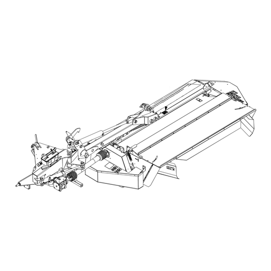
6 - WORKING OPERATIONS 6 - WORKING OPERATIONS###_6_### General information Implement overview It is possible only to connect the GXS 2805P and GXS 3205P implements at the rear of the tractor. The GXS has working widths 2.4 – 3.2 m (7.87 – 10.50 ft). More- over the GXS 2805P and GXS 3205P are equipped with conditioner with polyethylene (PE) fingers. -
Page 60: Friction Clutch
6 - WORKING OPERATIONS Friction clutch To ensure a long life for your tractor and implement, the implement is equipped with a friction clutch on the Power Take-Off (PTO) drive shaft between the tractor and the implement. The purpose of the friction clutch is to protect the transmis- sion from overload when you work in the field and when you start the implement (connection of the PTO). -
Page 61: Twisted Blades
6 - WORKING OPERATIONS Twisted blades WARNING Knife hazard! Use care handling sharp components. Always wear appropriate Personal Protective Equip- ment (PPE), including heavy gloves. Failure to comply could result in death or se- rious injury. W0274A Twisted blades (1) are reversible. You can turn the blade, but the blade must remain on the same disc. -
Page 62: Disc And Blades - Q+ System
ZEIL18HT00339AA erties and expose you and others to serious risks. NOTICE: Replace damaged blades, discs and blade hold- ers with original KONGSKILDE spare parts to obtain a safe operation. NOTE: Always lower the cutting unit to the ground before you replace blades, blade holders, discs and the like. - Page 63 6 - WORKING OPERATIONS Blade holder NOTE: Check the following points after the collision with foreign matter, after the replacement of blades and the first time you use the implement. Replace the blade holder if: • The blade pin (1) is not in contact with the disc. •...
-
Page 64: Working Position
6 - WORKING OPERATIONS Working position Conversion of the implement to working position takes place in reverse order of the conversion to transport posi- tion. NOTICE: Before you place the implement in working po- sition, you must check that there are no persons in the danger zone and that there is no risk of collision with ob- jects near the implement. -
Page 65: Relief Of Cutter Bar
6 - WORKING OPERATIONS Relief of cutter bar A low ground pressure spares the grass roots, reduces crop contamination, minimizes implement wear and re- duces fuel consumption. In general you must always work with the lowest possible ground pressure. On uneven ground a light implement may however cause the cutting unit to move up and down, which may result in uneven stubbles. - Page 66 6 - WORKING OPERATIONS The pressure gauge (2) indicates the pressure in the sys- tem. The adjustment of the pressure during working will be a matter of individual experience and depends on the implements weight and the ground conditions. A good start is obtained as follows: 1.
-
Page 67: Headland Position
6 - WORKING OPERATIONS Headland position When you lift the cutting unit from working position to headland position, the travel of the lifting is limited so that the cutting unit stops to a certain height. The valve (1) limits the travel of the lifting cylinder. The valve (1) is controlled by an arm (2) running on a cam track (3). -
Page 68: Hydraulic Stone Release
6 - WORKING OPERATIONS Hydraulic stone release All implements are equipped with a stone release which makes it possible for the cutting unit to swivel backwards in case of collision with an obstacle. This stone release is at the back of the suspension. NOTE: The stone release only works when you drive for- wards. -
Page 69: Stone Release
6 - WORKING OPERATIONS Stone release The GXS 2805P and GXS 3205P implements are equipped with a stone release which makes it possible for the cutting unit to swivel backwards in case of collision with an obstacle. This stone release is at the back of the suspension. -
Page 70: Working In The Field
6 - WORKING OPERATIONS Working in the field Before you work in the field, connect the implement cor- rectly. Check that the cutting unit is in working position and adjust the relief correctly as described in the previous sections. Connect the Power Take-Off (PTO) carefully and increase to the correct number of Revolutions Per Minute (RPM) before you work in the crop. - Page 71 6 - WORKING OPERATIONS A forward inclination of about 3° results in a theoretical stubble height (b) of 27 mm (1.06 in). ZEIL18HT00825AA The forward or backward inclination of the suspension should not exceed 3° since this would result in a devi- ation of the PTO shaft and consequently vibrations and increased wear.
-
Page 72: Conditioner
6 - WORKING OPERATIONS Conditioner All the implements are equipped with a conditioner rotor with polyethylene (PE) fingers. The conditioner rotor ro- tates with 860 RPM. To adjust the degree of conditioning, change the distance between the conditioner plate (1) and the conditioner fin- gers (2). - Page 73 6 - WORKING OPERATIONS Equipment for wide spreading (top dry) The equipment for wide spreading consists of a plate (5) which is installed behind the conditioner rotor. The equipment for wide spreading makes it possible to spread the crop instead of laying a swath and to optimize the drying.
- Page 74 6 - WORKING OPERATIONS If you wish a wide spreading, place the handle (6) in the active position (B) to fold down the plate (5). ZEIL18HT00331AA ZEIL18HT00563AA 6-16...
-
Page 75: Maintenance
7 - MAINTENANCE MAINTENANCE###_7_### General information Recommendations WARNING Avoid injury! Always do the following before lubricating, maintaining, or servicing the ma- chine. 1. Disengage all drives. 2. Engage parking brake. 3. Lower all attachments to the ground, or raise and engage all safety locks. 4. - Page 76 7 - MAINTENANCE When you repair or maintain the implement it is especially important to ensure the correct personal safety. There- fore, always park the tractor (if mounted) and the imple- ment safely (see Page 2-10). Always disengage the Power Take-Off (PTO) drive shaft, activate the parking brake and stop the tractor engine be- fore you: •...
- Page 77 7 - MAINTENANCE Hydraulic system When replace parts of the hydraulic system, always make sure that the cutting unit rests on the ground. Remember to relieve the oil pressure before you work with the hydraulic system. Hydraulic hoses must be checked before each use, and minimum once a year.
-
Page 78: Torque
7 - MAINTENANCE Torque Minimum hardware tightening torques (in N m or lb in /lb ft) for normal assembly applica- tions unless otherwise stated The minimum hardware tightening torque on drawings, in specifications, etcetera have priority. In the following tables, torque specifications are shown following the standard ENS7001, applicable for material class 8.8 and material class 10.9. - Page 79 7 - MAINTENANCE Flange head bolt/Flange nut Nominal Class 10.9 in N m (lb ft) Size 2.0 N·m (1.5 lb ft) 4.6 N·m (3.4 lb ft) 9.4 N·m (6.9 lb ft) 15.9 N·m (11.7 lb ft) 38.7 N·m (28.5 lb ft) 76.5 N·m (56.4 lb ft) 134 N·m (98 lb ft) 213 N·m (157 lb ft)
- Page 80 7 - MAINTENANCE Metric hex nuts and locknuts, Classes (CL) 05 and upward NHIL14RB00663AA Metric hex nut identification markings • (1) – Manufacturer's identification • (3) – Property class • (2) – Clockwise type markings indicate property class and may include manufacturer identification (if applied), Example: property marks 240°...
-
Page 81: Torque For Class 12.9
7 - MAINTENANCE Torque for class 12.9 Bolts of quality 12.9 are used on the implements. Make sure to use the same type of bolts and nuts to replace bolts and nuts of quality 12.9. It is easier to torque bolts and nuts to correct value of torque if you lubricate bolts and nuts with oil. -
Page 82: Fluids And Lubricants
7 - MAINTENANCE Fluids and lubricants KONGSKI- International KONGSKILDE Capacity Lubricant grade Item LDE specifi- specification brand name cation M1C 137-A Grease fittings As required NLGI 2 M1C 75-B Cutter bar 2.5 L API GL-5 SAE 85W-140 (0.66 US gal) -
Page 83: Maintenance Planning
7 - MAINTENANCE Maintenance planning Maintenance chart Lubricate Check Change fluid Replace Tighten Adjust Maintenance action Page no. After the first 3 hours of operation Bolts and fittings 7-10 After the first 50 hours of operation Cutter bar - oil change 7-10 Bevel gearbox above the cutter bar - oil change 7-11... -
Page 84: After The First 3 Hours Of Operation
7 - MAINTENANCE After the first 3 hours of operation Bolts and fittings Torque again all the bolts, the nuts and the fasteners after the first 3 h of work. After the first 50 hours of operation Cutter bar - oil change Perform the first oil change in the cutter bar after 50 h of work. -
Page 85: Bevel Gearbox Above The Cutter Bar - Oil Change
7 - MAINTENANCE Bevel gearbox above the cutter bar - oil change Perform the first oil change of the bevel gearbox above the cutter bar after 50 h of work. See Page 7-21. 7-11... -
Page 86: Bevel Gearbox At The Headstock - Oil Change
7 - MAINTENANCE Bevel gearbox at the headstock - oil change Perform the first oil change of the bevel gearbox at the headstock after 50 h of work. See Page 7-22. 7-12... -
Page 87: Daily Inspection
7 - MAINTENANCE Daily inspection Cutter bar - oil check NOTE: Check the oil level every day during the harvesting season at one of the plugs. NOTICE: Always clean the area around the cutter bar in- spection/fill plugs before you check the oil level to prevent contamination of the gear oil. - Page 88 7 - MAINTENANCE 3. On the cutter bar there are two plugs (3) for the oil check and filling. Remove both the plugs to check the oil level at each plug. The plugs are: • On GXS 2805P between the second and the third disc and between the fifth and the sixth disc.
-
Page 89: Every 40 Hours
7 - MAINTENANCE Every 40 hours Power Take-Off (PTO) - Grease Perform the lubrication every 40 h of work. Lubricant NLGI 2. Prior operation: Place the implement in safe conditions for maintenance. Lubricate the grease fittings indicated in the chart be- low. -
Page 90: Lubrication Chart
7 - MAINTENANCE Lubrication chart Perform the lubrication every 40 h of work. Lubricant NLGI 2. Prior operation: Place the implement in safe conditions for maintenance. Lubricate the grease fittings indicated in the chart be- low. ZEIL18HT00813FA 7-16... -
Page 91: Every 80 Hours
7 - MAINTENANCE Every 80 hours Bevel gearbox above the cutter bar - oil check To check the oil level proceed as follows: 1. Check the oil level through the inspection point (1). The oil level should be even with the oil level inspection point (1). -
Page 92: Bevel Gearbox At The Headstock - Oil Check
7 - MAINTENANCE Bevel gearbox at the headstock - oil check To check the oil level proceed as follows: 1. Check the oil level through the inspection point (1). The oil level should be even with the oil level inspection point (1). -
Page 93: Every 200 Hours
7 - MAINTENANCE Every 200 hours Cutter bar - oil change NOTE: Use SAE 85W-140 or an equivalent gear oil to maintain the cutter bar oil level. The approximate oil capacity is: • For GXS 2805P: 2.5 L (0.7 US gal). •... - Page 94 7 - MAINTENANCE 8. Remove the drain plug (5). The plug (5) for draining of oil is in the left-hand side of the cutter bar on the outermost guide shoe. Allow all of the oil to drain out of the cutter bar. 9.
-
Page 95: Every 600 Hours
7 - MAINTENANCE Every 600 hours Bevel gearbox above the cutter bar - oil change Use SAE 80W90 to maintain the oil level. The oil capacity is approximately 0.90 L (0.24 US gal). 1. Position a catch pan under the gearbox and remove the drain plug (3). -
Page 96: Bevel Gearbox At The Headstock - Oil Change
7 - MAINTENANCE Bevel gearbox at the headstock - oil change NOTE: Perform the oil change at least once a year. Use SAE 80W90 to maintain the oil level. The oil capacity is approximately: • 1.1 L (0.3 US gal) for 540 RPM. •... -
Page 97: Every Six Years
7 - MAINTENANCE Every six years Hydraulic hoses WARNING Escaping fluid! Do not disconnect hydraulic quick coupler under pressurized conditions. Make sure all hydraulic pressure is removed from the system before disconnecting hydraulic quick coupler. Failure to comply could result in death or serious injury. W0095A WARNING Escaping fluid! -
Page 98: As Required
7 - MAINTENANCE As required Maintaining the friction clutch Maintain the friction clutch at regular intervals. Air the clutch before you run a new implement. At the same time check the clutch after any long period of standstill, especially after the storage, before you use the imple- ment for the first time in the season. -
Page 99: Power Take-Off For The Cutter Bar
7 - MAINTENANCE Power Take-Off for the cutter bar The Power Take-Off (PTO) for the cutter bar should run with minimum angular deviation. Therefore a special tool is available to place the bevel gearbox precisely in relation to the cutter bar. If you do not have this special tool, check that the de- viation from the vertical line at (1) and (2) is as small as possible and maximum with a tolerance of 3 mm... -
Page 100: Control Of Balance
7 - MAINTENANCE Control of balance When you drive in the field always pay attention if the implement starts vibrating more than usually or if the implement has jarring sounds. NOTE: The first time you start the implement pay attention to vibrations and noise to have a standard of comparison later. -
Page 101: Replacement Of Blades - Q+ System
7 - MAINTENANCE Replacement of blades – Q+ system CAUTION Cutting hazard! Use care handling sharp components. Always wear appropriate Personal Protective Equipment (PPE), including heavy gloves. Failure to comply could result in minor or moderate injury. C0139A Prior operation: Place the implement in safe conditions for maintenance. - Page 102 7 - MAINTENANCE 5. When you install a blade (5), place the blade correctly on the pin (6) of the blade holder (4), then you can slacken the tool (1) and let it go back up. 6. The replacement tool (1) must, by the force of the blade holder (4) only, end up in the same position as before you replaced the blade (5).
-
Page 103: Replacement Of Discs
7 - MAINTENANCE Replacement of discs DANGER Moving parts! Install all covers, panels, and guards after servicing or cleaning the machine. Never operate the ma- chine with covers, panels, or guards removed. Failure to comply will result in death or serious injury. D0119A WARNING Avoid injury and/or machine damage! -
Page 104: Replacement Of Hubs
7 - MAINTENANCE Replacement of hubs DANGER Moving parts! Install all covers, panels, and guards after servicing or cleaning the machine. Never operate the ma- chine with covers, panels, or guards removed. Failure to comply will result in death or serious injury. D0119A WARNING Avoid injury and/or machine damage! - Page 105 7 - MAINTENANCE 5. Reinstall the discs with an angle (A) equal to 90° stag- gered in relation to each other. ZEIL18HT00047AA After you complete the installation, turn the discs a mini- mum one complete revolution by hand in order to check that no parts collide.
-
Page 106: Storage
7 - MAINTENANCE Storage Pressure washing Before you use pressure washing, clean the implement with compressed air. NOTE: Legislation in certain countries and good practice requires special treatment of waste water through sed- imentation and oil separation and controlled removal of residues. -
Page 107: End Of Season Service
7 - MAINTENANCE End of season service When the season is over, prepare the implement for the storage immediately. To prepare the implement for winter storage: 1. Clean the implement thoroughly. Dust and dirt absorb moisture and moisture increases the formation of rust. 2. -
Page 108: Ordering Parts And / Or Accessories
Order and install the spare parts and/or accessories at once before the next season. When you order spare parts, always make sure to give your KONGSKILDE dealer the model number and the Product Identification Number (PIN) of your implement. See “Product identification” in Chapter 1 of this opera- tor’s manual. -
Page 109: Troubleshooting
8 - TROUBLESHOOTING TROUBLESHOOTING###_8_### Fault code resolution Driving tips and fault finding Problem Possible Cause Correction Uneven stubble or bad The number of Revolutions Per Minute Check that the number of rotations of the cut. (RPM) of the tractor is too low. tractor Power Take-Off (PTO) is correct. - Page 110 8 - TROUBLESHOOTING...
-
Page 111: Specifications
9 - SPECIFICATIONS SPECIFICATIONS###_9_### Dimensions ZEIL18HT00303GA Dimension GXS 2805P GXS 3205P 1.49 m (4.89 ft) 1.49 m (4.89 ft) 3.65 m (11.98 ft) 3.99 m (13.09 ft) 0.27 m (0.89 ft) 0.27 m (0.89 ft) 1.95 m (6.40 ft) 1.95 m (6.40 ft) 4.14 m (13.58 ft) 4.48 m (14.70 ft) -
Page 112: Technical Data
9 - SPECIFICATIONS Technical data Technical data GXS 2805P GXS 3205P 2.8 m 3.2 m Working width (9.19 ft) (10.50 ft) 54 kW 66 kW Power requirement, minimum (73.42 Hp) (89.73 Hp) 3-point linkage Category III Power Take-Off (PTO) type 1 3/8”... -
Page 113: Fluids And Lubricants
9 - SPECIFICATIONS Fluids and lubricants KONGSKI- International KONGSKILDE Capacity Lubricant grade Item LDE specifi- specification brand name cation M1C 137-A Grease fittings As required NLGI 2 M1C 75-B Cutter bar 2.5 L API GL-5 SAE 85W-140 (0.66 US gal) - Page 114 9 - SPECIFICATIONS...
-
Page 115: 10 - Accessories
10 - ACCESSORIES 10 - ACCESSORIES###_10_### General information Accessories or optional equipment listed hereafter may be part of the standard equipment for certain countries. Some of these accessories or options may not be avail- able in certain markets. Category II hitch pin Replace factory fitted category III hitch pin (1) if the tractor can only be equipped with category II links. -
Page 116: Hydraulic Valve Block
10 - ACCESSORIES Hydraulic valve block The hydraulic valve block is a manual controlled selector valve for hydraulic functions of the implement. The oper- ator can activate the block via a rope. The hydraulic valve block reduce the number of the hy- draulic valves needed of the tractor (from three outlets to two). -
Page 117: 11 - Forms And Declarations
11 - FORMS AND DECLARATIONS 11 - FORMS AND DECLARATIONS###_11_### EC Declaration of Conformity EF-overensstemmelseserklæring/ EG-Konformitätserklärung/ EC Declaration of Conformity/ Déclaration CE de con- formité/ Dichiarazione CE di conformita/ EG Verklaring van Overeenstemming/ EG-försäkran om överensstämmelse/ EY-vaatimustenmukaisuusvakuutus/ Declaración de conformidad CE/ Deklaracja Zgodności WE./ Декларация за съответствие... - Page 118 11 - FORMS AND DECLARATIONS ZEIL19TL0017EA - er i overensstemmelse med Maskindirektivets bestemmelser (Direktiv 2006/42/EF) og hvis relevant også bestem- melserne i EMC-direktivet 2014/30/EU - In übereinstimmung mit den Bestimmungen der Maschinen-Richtlinie 2006/42/EG und wenn erforderlich auch mit der EMC-Richtlinie 2014/30/EU hergestellt wurde. - is in conformity with the provisions of the Machinery Directive 2006/42/EC and if relevant also the provisi¬ons of the EMC Directive 2014/30/EU.
- Page 119 11 - FORMS AND DECLARATIONS - z določili Direktive o strojih 2006/42/ES ter, če je to relevantno, tudi z določili EMC Direktive 2014/30/EU. - παραμένει σύμφωνη με τους όρους της Οδηγίας περί Μηχανών 2006/42/ΕΚ και σε περίπτωση που αυτό εφαρμόζεται και...
- Page 120 11 - FORMS AND DECLARATIONS 11-4...
- Page 121 Index ###_Index_### Access to implement components........Bevel gearbox above the cutter bar - oil change ......7-11, 7-21 Bevel gearbox above the cutter bar - oil check .
- Page 122 Legal obligations ......... Light kit for horizontal transport position .
- Page 124 Printed in U.S.A. Printed in Italy Kongskilde is a trademark registered in the United States and many other countries, owned or licensed to CNH Industrial N.V., its subsidiaries or a liates. © 2018 CNH Industrial America LLC. All Rights Reserved.
Need help?
Do you have a question about the GXS 2805 P and is the answer not in the manual?
Questions and answers