Table of Contents
Advertisement
C
ountry Flame Technologies
A Division of American Products, LLC
900 George Street
Marshfield, MO 65706
417-859-0990
417-859-0192
www.countryflame.com
COUNTRY FLAME TECHNOLOGIES
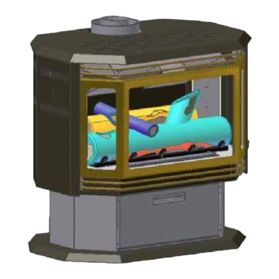
BAYVUE DIRECT VENT GAS STOVE
MODEL DV 30 & DV 46
NATURAL GAS OR PROPANE CAPABLE
WARNING:
exactly, a fire or explosion may result causing property damage, personal injury
or loss of life.
•
•
•
•
•
Do not store or use gasoline or any flammables (vapors or liquids) in the vicinity of
this or any other appliance.
Installation and repair must be performed by a qualified service person or gas supplier.
© 2004
If the directions contained in this manual are not followed
IF YOU SMELL GAS
FOR YOUR SAFETY
Do not light any appliance.
Do not touch electrical switches; do not use the phone in your
building.
Immediately call the gas company from a neighbor's phone.
Follow gas company instructions.
Call the Fire Department if Gas Company doesn't answer.
FOR YOUR SAFETY
USA & CANADA TEST STANDARD:
Harmonized ANSI Z21.50 - 2000
CSA 2.22 – 2000, CAN/CGA 2.17
TESTED BY:
WARNOCK HERSEY
Suitable for Bedroom
Installation
COUNTRY FLAME
Advertisement
Table of Contents
Troubleshooting

Related Manuals for Country Flame Bayvue DV 30


Summary of Contents for Country Flame Bayvue DV 30
-
Page 1: Country Flame
COUNTRY FLAME TECHNOLOGIES BAYVUE DIRECT VENT GAS STOVE MODEL DV 30 & DV 46 NATURAL GAS OR PROPANE CAPABLE ountry Flame Technologies A Division of American Products, LLC 900 George Street Marshfield, MO 65706 417-859-0990 417-859-0192 www.countryflame.com WARNING: If the directions contained in this manual are not followed exactly, a fire or explosion may result causing property damage, personal injury or loss of life. -
Page 2: Table Of Contents
INTRODUCTION ... 3 SAFETY INFORMATION ... 4 INSTALLATION, GENERAL... 5 PRESSURE TESTING... 5 ALTITUDE LIMITATIONS... 6 GAS SUPPLY CONNECTION ... 6 MINIMUM/MAXIMUM Btu RATES ... 7 CLEARANCES ... 7 MINIMUM CLEARANCES ... 9 CEILING CLEARANCES ... 9 TOOL LIST ... 9 UNPACKING... - Page 3 SNORKEL VENT ... 30 VERTICAL VENT... 30 CATHEDRAL CEILINGS... 31 MAINTENANCE ... 32 CLEANING BURNERS AND CONTROLS ... 32 REPLACE OLD EMBERS ... 32 CHECK FLAME AND PILOT ... 33 GLASS CLEANING ... 33 CHECK VENT SYSTEM ... 33 GLASS-CERAMIC SPECIFICATIONS ... 34 GLASS REPLACEMENT ...
-
Page 4: Introduction
Each and every employee at Country Flame pledges to ensure each and every one of our customers has our commitment to product support. Product support is dedicated to ensuring our customers achieve the greatest level of satisfaction from the proper use of our products. -
Page 5: Safety Information
ANNUALLY, BY A CERTIFIED GAS PROFESSIONAL. The interior of a gas stove is subject to surface rust due to moisture in the combustion air as well as condensation created during the initial warm up and firing of the gas appliance. At a minimum, annually clean and repaint the interior surfaces to prevent deterioration. -
Page 6: Installation, General
The Bayvue DV installation must ensure adequate combustion air and ventilation air is available for proper stove operation. Refer to the venting section for further combustion air requirements. Installation must conform to local codes and gas supplier restrictions. In the absence of local codes, an installation must conform to the current National Fuel Gas Code which at the writing of this manual is ANSI Z223.1... -
Page 7: Altitude Limitations
Failure to follow the instructions contained in this manual will void the warranty and may present a fire hazard. Immediately, upon unpacking the product, report any glass or parts damaged, to both the shipping company and the local Country Flame Dealer. Country Flame... -
Page 8: Minimum/Maximum Btu Rates
Clearances around the appliance must allow for proper servicing of the product. If there is any question about clearances please contact Country Flame or a certified professional. Never reduce clearances below the minimums stated in this manual. - Page 9 Follow all sidewalls, overhang and ground clearances as stated in the instructions. Country Flame Technologies assumes no responsibility for the improper performance of the fireplace when the venting system does not meet requirements.
-
Page 10: Minimum Clearances
Unbolt the stove from the pallet. Discard pallet and packaging material. STEP 2 Open the stove door on the unit and unpack all components located inside the firebox. STEP 3 Inspect the interior and exterior of the stove for any shipping damage. -
Page 11: Log Placement
NATURAL GAS 0 – 2000 FEET FRONT BURNER 1/8 INCH MIDDLE BURNER 3/16 INCH REAR BURNER 3/8 INCH PROPANE 0 – 2000 FEET FRONT BURNER 1/8 INCH MIDDLE BURNER FULL OPEN REAR BURNER FULL OPEN TABLE 4: AIR SHUTTER ADJUSTMENT LOG PLACEMENT The ceramic logs provided with this appliance are extremely fragile. - Page 12 It should be a very clean burn as shown in FIGURE 5d. Contact a local Country Flame Dealer or certified professional if there is any issue with the flame appearance. Version 1.0h...
-
Page 13: Control Panel Access
The Bayvue DV can sit on a raised hearth as long as all chimney pipe and all stove minimum clearances are maintained. VALVE ASSEMBLY REMOVAL From time to time, it may be necessary to remove the valve assembly. -
Page 14: Fuel Conversion Kits
This information is provided for homeowner reference but all conversions are to be completed by a certified professional. In the event of any problem with a Country Flame conversion kit or the installation of the kit, please contact a local authorized Country Flame Dealer or contact Country Flame directly to obtain additional information and assistance in properly resolving the problem. -
Page 15: Pr Conversion Kit Bv-4604 Contents
NOTE: Conversion kits are available only for natural gas and propane fuel. NOTE: A Country Flame conversion kit is to be installed only by certified service technicians. NOTE: Check kit contents for all parts. Do not attempt conversion with items missing. -
Page 16: Propane Conversion Kit
Bayvue DV30P to DV46N Kit BV-3003 PROPANE CONVERSION Bayvue DV appliances are shipped from the Country Flame factory set for 46,000 Btu Natural Gas fuel usage; however, conversion kits may be purcahsed from Country Flame to convert the Bayvue DV to different fuels (propane or natural gas) or lower the heat outuput to 30,000 Btu. - Page 17 STEP 5 Refer to FIGURE 8. Ensure that the rubber gasket (Item D) is properly positioned and install the new HI/LO pressure regulator assembly to the valve using the supplied screws (Item E). Tighten screws securely. STEP 6 Attach the enclosed "conversion" label near the certification label. STEP 7 Re-attach all wiring to the fan control knob and the piezoelectric igniter.
- Page 18 STEP 13 Refer to FIGURE 11, Note (X). The piezoelectric igniter cannot be installed incorrectly unless it is damaged. The piezoelectric igniter should be in a parallel plane to the pilot flame diffuser body. Each time the igniter button is pressed, a blue arc should occur from the piezoelectric igniter to the pilot flame diffuser body.
-
Page 19: Intake And Exhaust Conditions
STEP 14 Open the gas supply and perform gas leak test. One of the best methods used to check for gas leaks is soap bubbles. Soap bubbles are made by mixing liquid detergent with a little water and shaking vigorously to create soap bubbles. Cover the gas pipe joint or valve component with these soap bubbles. -
Page 20: Fan Installation
DIRECT VENT INSTALLATION GENERAL Country Flame Bayvue DV product is approved for side wall vent or vertical vent through a roof. Only Simpson Dura Vent chimney components or Selkirk Model Direct-Temp chimney components may be used with this product. Simpson Dura Vent chimney vent products are listed in this manual to assist with vent installation selection. -
Page 21: Installation Precautions
The Simpson Dura Vent Direct Vent System and the Selkirk Model Direct-Temp System are engineered products that have been designed and tested for use with the Country Flame Bayvue DV product. The chimney pipe product warranty will be voided and serious fire, health, or other safety hazards may result from any of the following actions: Installation of any damaged venting component. -
Page 22: Basic Vent Kits
Country Flame Part # Dura-Vent Part # CF-11010 908B CF-11011 907B CF-11012 CF-11013 906B CF-11014 CF-11015 904B CF-11016 CF-11017 903B CF-11018 CF-11019 902B CF-11020 911B CF-11030 CF-11031 945B CF-11032 CF-11033 990B CF-11051 CF-11058 CF-11052 CF-11055 CF-11056 CF-11054 CF-11057 CF-11043 CF-11044... -
Page 23: Installation Plan
Failure to provide adequate combustion air will cause operational problems, increased maintenance issues, and potential failure of the gas stove to perform to its designed standard. For specific details on combustion air requirements, refer to the current NFPA-54 (natural gas) or NFPA-58 (propane) and the current ANSI Z223.1 standards. - Page 24 Now multiply 46 times the 40 cubic feet (ventilation air only) requirement which equals 1,840 cubic feet of room space. If a Country Flame vented appliance was being installed, the minimum room size would increase to 2,300 square feet as combustion air would have to be supplied by the room. Always use the highest Btu/H rating of an appliance to determine the maximum fresh air requirement before an appliance is placed in a room.
-
Page 25: Direct Vent Termination
VERTICAL TERMINAL Vertical terminals are measured from the top of the stove and can be no more than a maximum of 34 feet from stove to flue cap. Where floors or attic space are penetrated by chimney vent pipe, safety requires that a round support box/fire stop be installed to ensure minimum clearances to any combustible material is maintained. - Page 26 STEP 3. With the adapter and pipe attached to the stove, slide the stove into its correct location, and mark the wall for a 10" x 10" square hole. The center of the square hole should line up with the centerline of the horizontal pipe.
-
Page 27: Wood Screws
WOOD SCREWS Wall Penetration Heat Shield (Wall Thimble) Duravent Part #942 FIGURE 13: HORIZONTAL VENTING Fold and Sheet Metal Wall Screw Strap Thimble FIGURE 14: HORIZONTAL VENT FIGURE 16: ROUND SUPPORT BOX/WALL THIMBLE Version 1.0h Wall Thimble Strap FIGURE 15: DECORATIVE TRIM 10"... -
Page 28: Vertical And Horizontal Vent
VERTICAL AND HORIZONTAL VENT STEP 1. Determine the amount of horizontal run for a specific installation. Note the minimum vertical run and ensure it is met for a specific application as shown in FIGURE 17 below. STEP 2. FIGURE 18 or 19 provides the minimum vertical rise required for a specific horizontal run HORIZONTAL TOP FLUE INSTALLATION Min. -
Page 29: Vent Graphs
Determine which fuel graph chart is to be used. (Natural Gas or Propane) Determine the height from the top of the stove to the 7" elbow. Draw a horizontal line until it intersects with the slanted graph line. From the point of this intersection, draw a vertical line to the bottom of the graph. -
Page 30: Vent Graph (Cont'd)
VENT GRAPH (cont'd) Note: Maximum propane horizontal vent run is 13' (3960mm) when the vertical vent rise is 10' (3048mm) Note: Minimum vertical rise is 2' (908 mm) Note: Minimum horizontal run is 11" (279mm) on a vertical to horizontal installation. Note: Minimum wall thickness 4"... -
Page 31: Snorkel Vent
1" to combustibles. Frame the hole as shown in FIGURE 16. STEP 4 If the twist-lock adapter has not been installed on the stove by the manufacturer; install it now in accordance with the stove instruction manual. -
Page 32: Cathedral Ceilings
STEP 6 Continue to assemble lengths of pipe and elbows necessary to reach from the ceiling support box up through the roof line. Galvanized pipe and elbows may be utilized in the attic, as well as above the roof line. The galvanized finish is desirable above the roof line, due to its higher corrosion resistance. -
Page 33: Maintenance
Follow the general guidelines provided below for each specific maintenance task. If there are any questions about maintenance or proper service, contact the local Country Flame dealer or a certified service technician for clarification of any issue. -
Page 34: Check Flame And Pilot
TASK PERFORMED: Remove the door assembly by unhooking the four locks (2 locks on each side). Use a household glass cleaner or a Hearth Industry approved gas stove glass cleaner. Replace the door assembly and close the four locks to properly seal the door to the body of the Bayvue DV. -
Page 35: Glass-Ceramic Specifications
Flame gas fireplace doors use a KERA LITE Country Flame custom cuts each KERA LITE occur or should the glass-ceramic ever need replacement, contact Country Flame or a local authorized dealer for assistance. The glass-ceramic specifications are as follows: Manufacturer... - Page 36 10. The door assembly is a sealed unit. Refer to door seal section. Reread test procedures and check door seal. Perform test seal procedure to ensure door assembly fits properly to Bayvue DV body. Contact a local authorized Country Flame Dealer or a certified professional if there are any issues with the seal. WARNING: THIS PRODUCT IS A SEALED APPLIANCE.
-
Page 37: General Vent Inspection
Occasionally dry rag dust to keep the painted surface looking new. Paint can be touched up as needed. Clean the areas to be painted with fine steel wool. Remove all trim or cover all trim and controls with ® masking tape. Then, touch up the stove with Stove Bright high temperature stove paint. Version 1.0h... -
Page 38: Cleaning Plated Surfaces
FIGURE 24 below. If there is any concern about a proper seal or the condition of the door rope gasket or glass tape, contact a local authorized Country Flame Dealer or a certified technician for assistance. -
Page 39: Main Orifices
MAIN ORIFICES FIGURE 25, left view, illustrates the front burner spud orifice (Item A) unthreaded from the orifice holder (Item B). Do not over tighten the orifice spud. Do not leave the orifice spud finger tight as gas may leak from the loose fitting. -
Page 40: Relief Valve Inspecton
FIGURE 26, Item C shows the normal direction of travel of the relief valve. A spring provides tension to hold the relief valve against the body of the stove. Relief plates should be free to slide on the tracks provided, shown in FIGURE 26, as Item B in order to relieve any pressure buildup in the combustion chamber. -
Page 41: Sit 820 Nova Mv Gas Control Valve
SIT 820 NOVA mV GAS CONTROL VALVE The 820 Gas Control Valve is shown below in FIGURE 27. The left knob controls the ON/PILOT/OFF functions. The right knob controls the manifold pressure to the burners and is labeled HI/LO. There is a PILOT ADJSUT screw that should only be adjusted by a certified technician. The SIT 820 has an input pressure test port labeled IN. -
Page 42: Warranty
Country Flame Technologies one year warranty program. Country Flame Technologies will not be responsible for any alteration to the unit which causes sooting that results in damage to the interior or exterior of the building in which this appliance is installed. -
Page 43: Trouble Shooting Guide
TROUBLE SHOOTING GUIDE SYMPTOM Pilot will not light No spark at the pilot burner Spark gap is incorrect No gas at the pilot burner Out of Propane Pilot goes out when System is not correctly purged the gas knob is Out of Propane gas released Pilot flame is not large enough... -
Page 44: Trouble Shooting Guide (Cont'd)
TROUBLE SHOOTING GUIDE (cont’d) SYMPTOM Burner pops off Dirt in the burner orifice Improper gas pressure Flame in mixing Dirt in burner orifice tube Improper gas pressure Not heating Dirt in the burner orifice properly (Not Wrong orifice enough or too Too much draft slow) Improper gas pressure... -
Page 45: Parts List
PARTS LIST PART NUMBER BV-3001 BV-3002 BV-3003 BV-3004 BV-4601 BV-4602 BV-4603 BV-4604 BV-4609 BV-4610 BV-4611 BV-4612 BV-4613 BV-4614 BV-4617 BV-4618 BV-4619 BV-4620 BV-4621 BV-4622 BV-4623 BV-4624 BV-4625 BV-4626 BV-4627 BV-4628 BV-4629 BV-4630 BV-4631 BV-4632 BV-4633 BV-4634 BV-4640 BV-4641 BV-4642 BV-4644 BV-4646 BV-4647 BV-4648... -
Page 46: Parts List (Cont'd)
GC-3934 GC-3989 All parts for the Bayvue DV product can be purchased by contacting a local authorized Country Flame Dealer. In the event there is no local Country Flame Dealer, contact Country Flame direct by writing, calling, or emailing at the following address:... -
Page 47: Operating Instructions
OPERATING INSTRUCTIONS FOR YOUR SAFETY READ BEFORE LIGHTING WARNING: If you do not follow these instructions exactly, a fire or explosion may result causing property damage, personal injury, or loss of life. The Bayvue DV has a pilot light system that must be lit by hand. Follow these instructions exactly, when lighting the pilot. -
Page 48: Safety Label
SAFETY LABEL Version 1.0h...
Need help?
Do you have a question about the Bayvue DV 30 and is the answer not in the manual?
Questions and answers